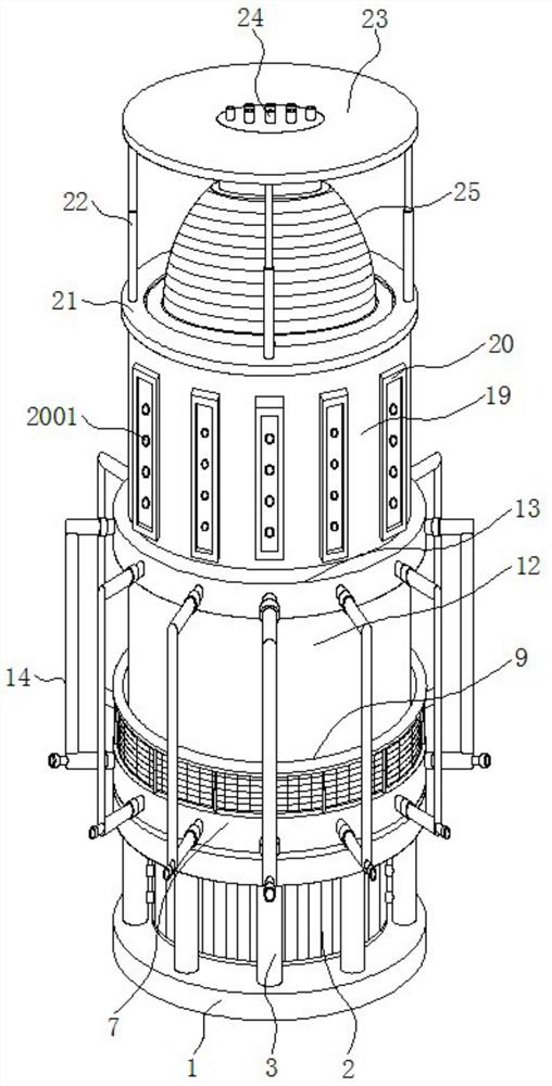
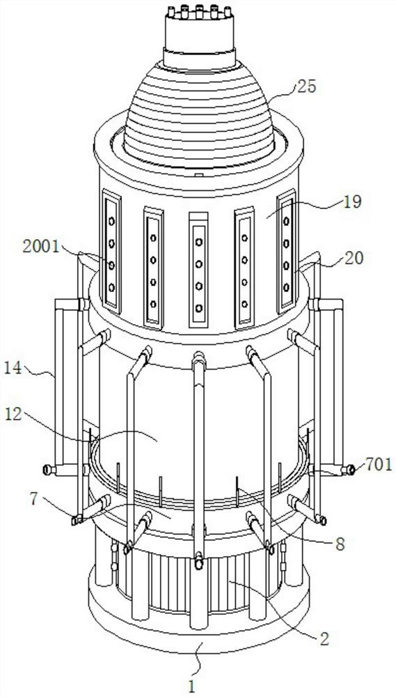
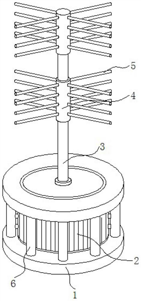
A blast type multi-chamber replacement powder mixer

A blast type, mixer technology, used in mixers, solid and solid mixing, mixed material pretreatment, etc., can solve the problems of large equipment load, low mixing efficiency, short service life, etc., achieve good heat dissipation protection, improve The effect of mixing speed and improving mixing efficiency

Active Publication Date: 2022-07-19
无锡诚智炼钢辅助材料有限公司
View PDF21 Cites 0 Cited by
  • Summary
  • Abstract
  • Description
  • Claims
  • Application Information

AI Technical Summary

Problems solved by technology

[0003] During the mixing process of the powder, it needs to be stirred continuously to obtain a uniformly mixed powder, but the way of stirring makes the equipment load larger, easy to damage, and the service life is not long
[0004] A powder mixing device disclosed in Chinese utility model patent CN206483428U, although the powder mixing device is provided with a feeding tank with a feeding port, it can ensure that the powder will not all enter the powder mixing tank at once Mixing, but slowly entering, thus effectively avoiding the phenomenon of powder agglomeration and ensuring the uniformity of powder mixing, and at the same time, the powder is mixed by setting a stepless variable speed motor to drive the screw mixing rod to rotate, It can improve the powder mixing efficiency and production efficiency. However, the powder mixing device only uses mechanical rotation to mix the powder, which has low mixing efficiency, large mechanical wear, short service life, low mixing efficiency, and difficult mixing quality. Guaranteed Disadvantages

Method used


Image

  • A blast type multi-chamber replacement powder mixer
  • A blast type multi-chamber replacement powder mixer
  • A blast type multi-chamber replacement powder mixer

Examples


Embodiment Construction

[0031] The technical solutions in the embodiments of the present invention will be clearly and completely described below with reference to the accompanying drawings in the embodiments of the present invention. Obviously, the described embodiments are only a part of the embodiments of the present invention, but not all of the embodiments.

[0032] In the description of the present invention, unless otherwise stated, "plurality" means two or more; the terms "upper", "lower", "left", "right", "inner", "outer" The orientation or positional relationship indicated by , "front end", "rear end", "head", "tail", etc. are based on the orientation or positional relationship shown in the drawings, and are only for the convenience of describing the present invention and simplifying the description, not An indication or implication that the referred device or element must have a particular orientation, be constructed and operate in a particular orientation, is not to be construed as a limit...


PUM


Abstract

The invention discloses a blast type multi-chamber replacement type powder mixer, which relates to the technical field of powder mixers, in particular to a base, a mixing cylinder, a blast mechanism, a feeding cylinder and a pressing mechanism. A motor is installed, the mixing cylinder is fixed above the support plate, and the blowing mechanism is arranged around the outside of the mixing cylinder at equal distances. The feeding cylinder is fixed above the connecting plate, and the pressing mechanism is arranged in the middle of the upper surface of the top plate. The blast type multi-chamber replacement powder mixer drives the stirring sleeve through the rotating shaft, so that the stirring rod on the stirring sleeve performs mechanical rotation, so as to achieve the purpose of stirring the powder by the stirring rod, and the refrigerant pipe is evenly arranged in the motor. The outside of the motor is used to take away the heat generated by the motor, so as to achieve the purpose of cooling the motor, so that the motor can get good heat dissipation protection and work more stably.

Description

technical field [0001] The invention relates to the technical field of powder material mixers, in particular to a blast type multi-cavity replacement type powder material mixer. Background technique [0002] Powder mixer is a kind of machine and equipment for mixing a variety of powder materials. It is widely used in many industries and is one of the necessary equipment to realize material mixing. There are many kinds of powder mixing equipment. Commonly used equipment are double helix cone mixer, horizontal gravityless mixer, horizontal coulter mixer, horizontal ribbon mixer, etc. [0003] During the mixing process of the powder, it is necessary to continuously stir to obtain a uniformly mixed powder, but the stirring method makes the equipment load larger, easy to damage, and has a short service life. [0004] A powder mixing device disclosed in Chinese utility model patent CN206483428U, although the powder mixing device is provided with a feeding slot with a feeding port...

Claims


Application Information

Patent Timeline
Patent Type & Authority Patents(China)
IPC IPC(8): B01F33/40B01F35/10B01F35/43B01F35/00B01F35/75B01F35/92B01F23/60B01F23/70
CPCB01F23/60B01F23/70B01F33/402B01F35/43B01F35/10B01F35/187B01F35/75465B01F2035/99B01F35/92
Inventor 刘步周郁立超
Owner 无锡诚智炼钢辅助材料有限公司
Why Eureka
Try Eureka