
Direct-current permanent magnet motor iron core

A permanent magnet motor and iron core technology, applied in the field of motor iron cores, can solve the problems of inability to replace coils and waste, and achieve the effect of easy disassembly and installation

Inactive Publication Date: 2020-09-08
皮芝青
View PDF1 Cites 0 Cited by
  • Summary
  • Abstract
  • Description
  • Claims
  • Application Information

AI Technical Summary

Problems solved by technology

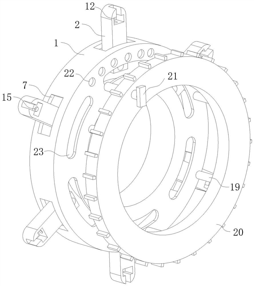
[0004] In order to make up for the deficiencies of the existing technology and solve the problem that the coil cannot be replaced directly after the coil is burned, and the iron core and the coil need to be replaced at the same time, resulting in waste, a DC permanent magnet motor iron core proposed by the present invention

Method used


Image

  • Direct-current permanent magnet motor iron core
  • Direct-current permanent magnet motor iron core
  • Direct-current permanent magnet motor iron core

Examples


Embodiment Construction

[0025] In order to make the technical means, creative features, goals and effects achieved by the present invention easy to understand, the present invention will be further described below in conjunction with specific embodiments.

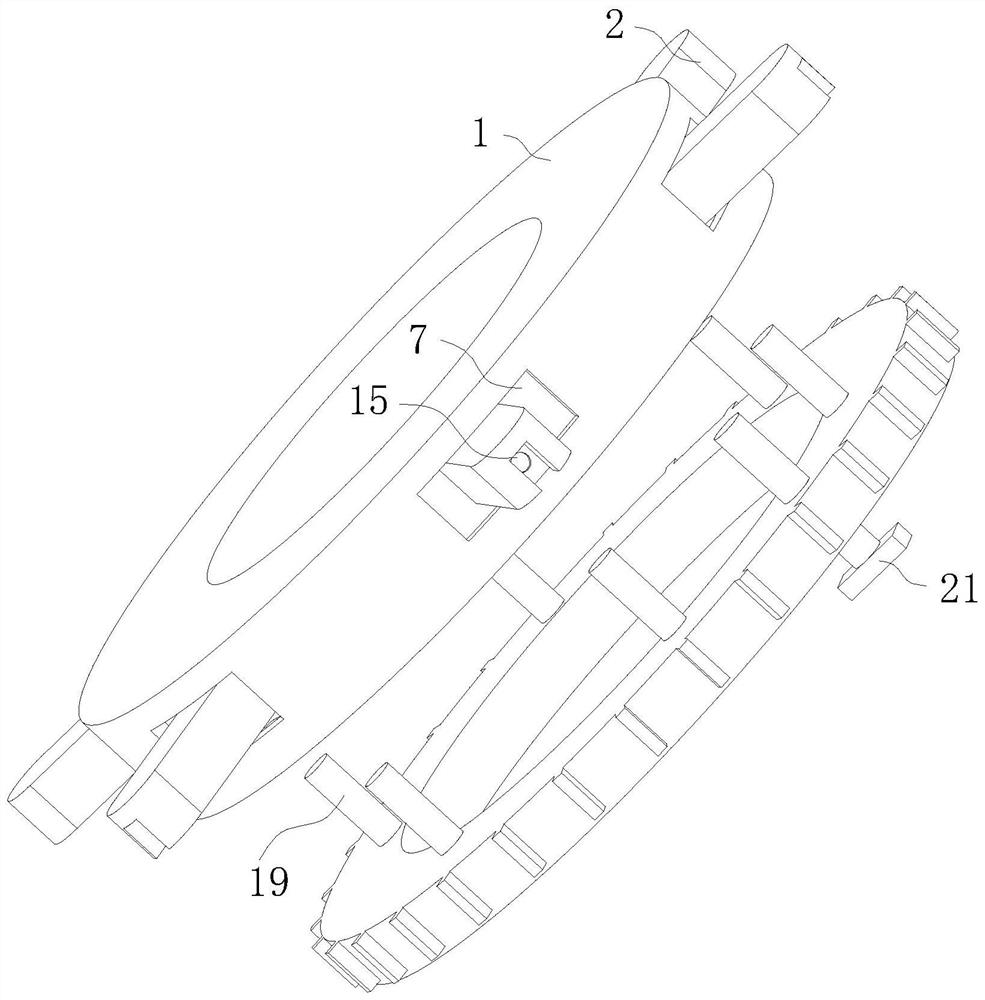
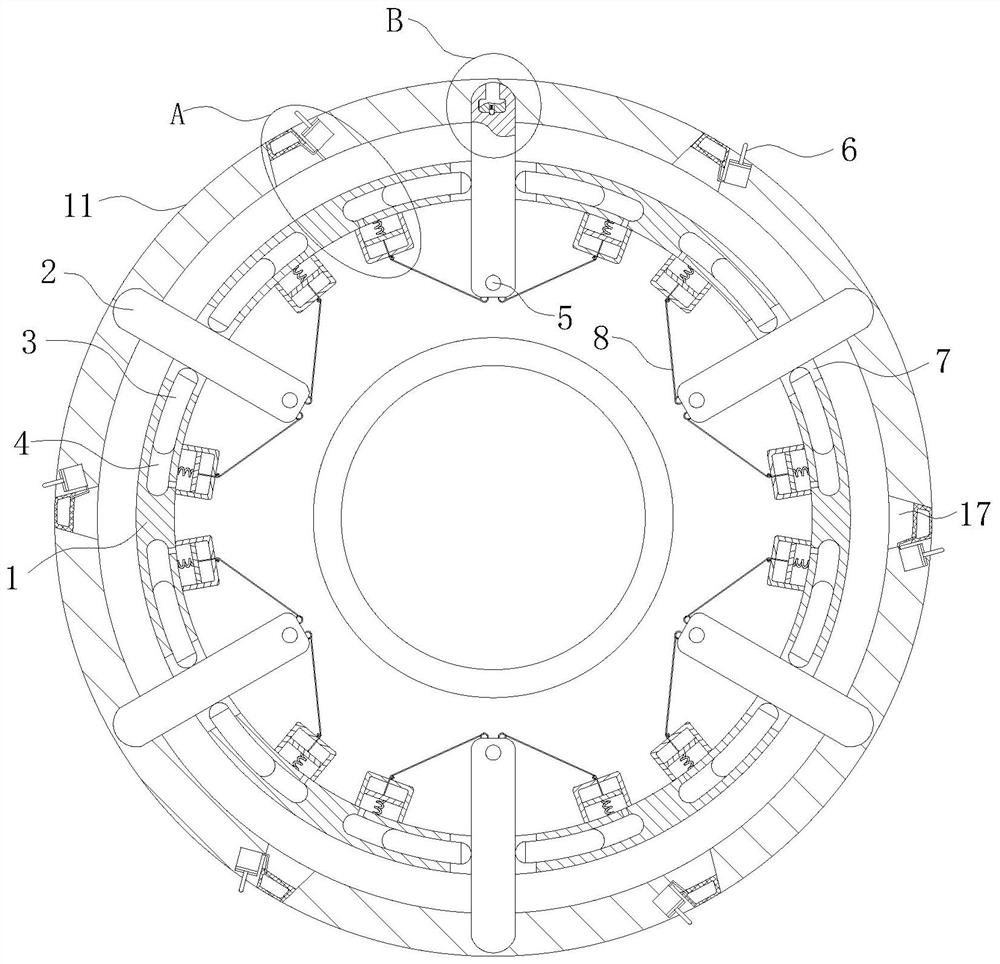
[0026] Such as Figure 1 to Figure 7 As shown, a DC permanent magnet motor core according to the present invention includes an iron ring 1, a winding rod 2, an arc-shaped clamping rod 3, an arc-shaped chute 4, a connecting hole 5, a pull cord 8, and a columnar groove body 9 and piston plate 10; the inside of the iron ring 1 is provided with an annular cavity; the outer edge of the iron ring 1 is evenly provided with several groups of arc-shaped through grooves 7 communicating with the annular cavity; The inside of the through groove 7 is inserted with a winding rod 2; the position close to the bottom end of the winding rod 2 is provided with a connecting hole 5; the side of the iron ring 1 is fitted with a rotating ring 20; the rotating ring 20 T...


PUM


Abstract

The invention belongs to the technical field of motor iron cores, and particularly relates to a direct-current permanent magnet motor iron core. The direct-current permanent magnet motor iron core comprises an iron ring, a winding rod, an arc-shaped clamping rod, a columnar groove body and a piston plate, wherein an annular cavity is formed in the iron ring; a plurality of groups of arc-shaped through grooves communicated with the annular cavity are uniformly formed in the outer edge of the iron ring; the winding rod is inserted into the arc-shaped through groove; a connecting hole is formed in the position, which is close to the bottom end, of the winding rod; a rotating ring is attached to the side face of the iron ring; a driving rod is fixedly arranged on the edge of the surface, whichis close to the iron ring, of the rotating ring; and the driving rod penetrates through the arc-shaped through groove in the iron ring and is inserted into the connecting hole in the winding rod. According to the invention, coil replacement is facilitated, the iron ring and the winding rod can be used as molds for coil production in a factory to produce coils in batches, a user can directly purchase finished coils conveniently and replace the coil by himself / herself when the coil is damaged, convenience and quickness are achieved, and a motor does not need to be sent back to a manufacturer tobe replaced.

Description

technical field [0001] The invention belongs to the technical field of motor iron cores, in particular to a DC permanent magnet motor iron core. Background technique [0002] The fixed part of the motor is called the stator, on which a pair of stationary main magnetic poles of DC excitation are installed; the rotating part is called the armature core, on which the armature winding is installed, and the induced electromotive force is generated after power-on, acting as Rotating magnetic field; after that, electromagnetic torque is generated for energy conversion. According to the shape of the stator winding and the way of embedded installation, the stator winding can be divided into two types: centralized and distributed according to the shape of the coil winding and the way of embedded wiring. [0003] The patent application number CN201911319778.8 proposes a DC permanent magnet motor iron core, including an iron core group, a flow guide mechanism, a limit mechanism, a clam...

Claims


Application Information

Patent Timeline
Patent Type & Authority Applications(China)
IPC IPC(8): H02K1/18H02K1/20
CPCH02K1/18H02K1/20
Inventor 皮芝青余来国
Owner 皮芝青
Learn More