
An amorphous alloy transformer

A technology of amorphous alloys and transformers, applied in the field of amorphous alloy transformers, can solve the problems of long service life of transformers, inability to know internal conditions, low operating temperature, etc.

Active Publication Date: 2021-07-06
INST OF APPLIED PHYSICS JIANGXI ACADEMY OF SCI
View PDF6 Cites 0 Cited by
  • Summary
  • Abstract
  • Description
  • Claims
  • Application Information

AI Technical Summary

Problems solved by technology

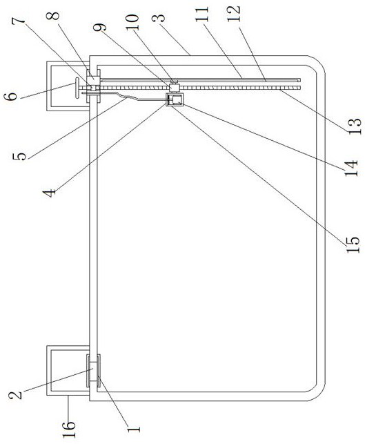
[0002] The amorphous alloy transformer is an energy-saving transformer developed in the 1970s. The biggest advantage of the amorphous alloy core distribution transformer is that it has extremely low no-load loss, energy saving, and high power efficiency. Save electricity consumption and reduce power plant power generation, relatively reduce CO2 SO2 waste gas emissions, reduce environmental pollution and greenhouse effect, maintenance-free, no pollution; low operating temperature, slow insulation aging, long service life of transformers, and amorphous alloys are practical There are also many problems to be solved in the field of transformers. Since alloy transformers are all sealed structures, there is a disadvantage that the internal conditions are inconvenient to observe, resulting in the inability to know the internal conditions.

Method used


Image

  • An amorphous alloy transformer
  • An amorphous alloy transformer

Examples


Embodiment Construction

[0014] Embodiments of the present invention are described in detail below, examples of which are shown in the drawings, wherein the same or similar reference numerals designate the same or similar elements or elements having the same or similar functions throughout. The embodiments described below by referring to the figures are exemplary only for explaining the present invention and should not be construed as limiting the present invention.

[0015] In describing the present invention, it is to be understood that the terms "center", "upper", "lower", "front", "rear", "left", "right", "vertical", "horizontal", The orientations or positional relationships indicated by "top", "bottom", "inner", "outer", etc. are based on the orientations or positional relationships shown in the drawings, and are only for the convenience of describing the present invention and simplifying the description, rather than indicating or implying the It should not be construed as limiting the invention ...


PUM


Abstract

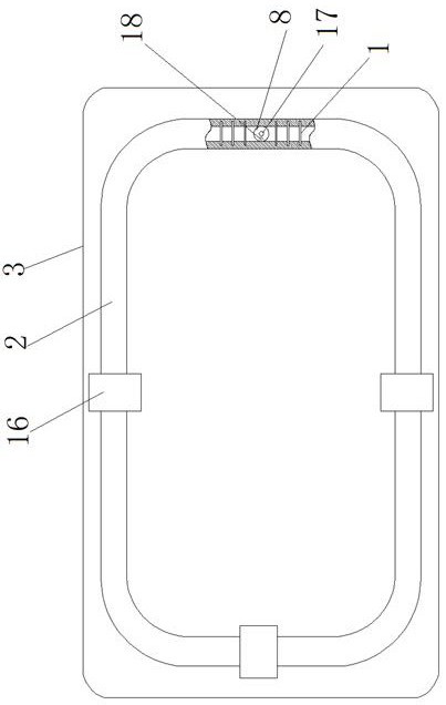
The present invention relates to the technical field of electric power equipment, in particular to an amorphous alloy transformer, which includes a casing. The top of the casing is provided with an annular mouth, and a rubber ring is arranged in the annular mouth. hole, a fixed block is installed in the fixed hole, the fixed block is provided with a mounting hole and a first wire hole, a bearing is installed in the mounting hole, a screw is installed in the inner ring of the bearing, and one end of the screw located inside the housing is threaded with a A positioning rod is provided on one side of the sleeve, a positioning rod is arranged on one side of the screw rod, a placement shell is installed on an end surface of the sleeve facing toward the center of the shell, and a camera is arranged inside the placement shell. The invention has a simple structure, and the internal conditions of the transformer can be photographed by the camera. The camera can move up and down through the rotation of the screw rod, and can rotate along the annular mouth, so that external personnel can fully know the internal conditions of the transformer and facilitate maintenance.

Description

technical field [0001] The invention relates to the technical field of power equipment, in particular to an amorphous alloy transformer. Background technique [0002] The amorphous alloy transformer is an energy-saving transformer developed in the 1970s. The biggest advantage of the amorphous alloy core distribution transformer is that it has extremely low no-load loss, energy saving, and high power efficiency. Save electricity consumption and reduce the power generation of power plants, relatively reduce CO2 SO2 waste gas emissions, reduce environmental pollution and greenhouse effect, maintenance-free, no pollution; low operating temperature, slow insulation aging, long service life of transformers, and amorphous alloys are practical There are also many problems to be solved in the field of transformers. Since alloy transformers are all sealed structures, there is a disadvantage that the internal conditions are inconvenient to observe, resulting in the inability to know th...

Claims


Application Information

Patent Timeline
Patent Type & Authority Patents(China)
IPC IPC(8): H01F27/40
CPCH01F27/40
Inventor 胡强张友亮王超敏吴丹康林萍谌昀
Owner INST OF APPLIED PHYSICS JIANGXI ACADEMY OF SCI
Learn More