Feedback device of control valve positioner

A technology of feedback device and positioner, which is applied in the direction of valve device, transmission device, belt/chain/gear, etc., can solve the problems of large control accuracy error, unsatisfactory basic error of control valve, and unsatisfactory control accuracy of actuator, etc., to achieve It is convenient for motion feedback and the effect of precise control

Active Publication Date: 2020-09-08
自贡新地佩尔阀门有限公司
View PDF9 Cites 0 Cited by
  • Summary
  • Abstract
  • Description
  • Claims
  • Application Information

AI Technical Summary

Problems solved by technology

[0005] More generally, the structure in which the linear stroke of the conventional actuator is converted into the angular stroke of the positioner feedback unit can satisfy its function in terms of the action form of the actuator, but the control accuracy error is large, that is, the linear stroke of the actuator is a unit distance, but the angle The stroke feedback magnetic strip is not a unit of rotation angle, which cannot meet the control accuracy of the actuator, nor can the basic error of the control valve.
[0006] At present, among similar products at home and abroad, basically all of them are attached figure 1 The structure shown; this structure also realizes the conversion of linear stroke and angular stroke between the valve stem and the positioner; the disadvantage is that it cannot achieve precise control and feedback of different opening positions

Method used


Image

  • Feedback device of control valve positioner
  • Feedback device of control valve positioner
  • Feedback device of control valve positioner

Examples


Embodiment 1

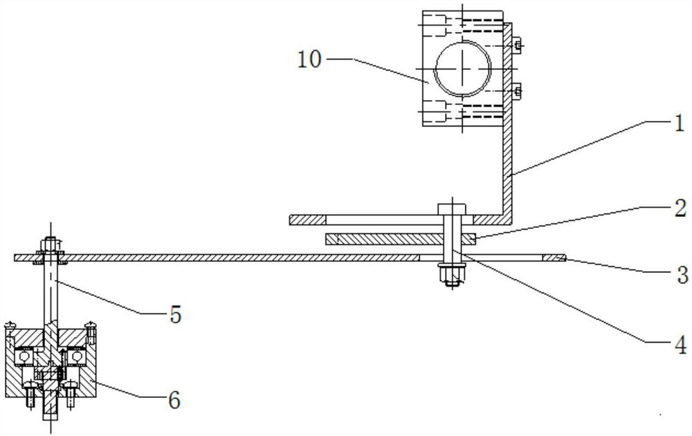
[0018] Embodiment 1: as Figure 1-Figure 2 As shown, a control valve positioner transmission device includes a feedback plate 1, a limit plate 2, a swing rod 3, a positioner 6 and a connecting rod 4; the feedback plate 1 is L-shaped, and a valve stem holder is fixed on one side 10. There is a feedback board chute 7 at the center of the other side along the length direction; the limit plate 2 is a rectangular plate, and its surface is provided with an arc-shaped limit groove 8 along the length direction; the front end of the swing rod 3 is provided with a The swing bar chute 9; the feedback board 1, the swing bar 3 and the limit plate 2 are connected by the connecting rod 4, and the connecting rod 4 passes through the swing rod chute 9, the limit slot 8 and the feedback plate chute 7 in turn, and the connecting rod 4 Can slide along the swing bar chute 9, the limit groove 8 and the feedback plate chute 7; the rear end of the swing bar 3 is fixed to the rotating shaft 5 of the l...


PUM


Abstract

The invention discloses a feedback device of a control valve positioner. The feedback device of the control valve positioner is characterized by including a feedback board, a limit board, a swing rod,a positioner and a connecting rod; the feedback board is L-shaped, one side of the feedback board is fixed with a valve stem fixator, and the other side of the feedback board is provided with a feedback board sliding groove at the center position in the length direction; the limit board is a rectangular board, and the surface of the limit board is provided with an arc-shaped limit groove in the length direction; the front end of the swing rod is provided with a swing rod sliding groove in the length direction; the feedback board, the swing rod and the limit board are connected by the connecting rod, the connecting rod passes through the swing rod sliding groove, the limit groove and the feedback board sliding groove in sequence, and the connecting rod can slide along the swing rod slidinggroove, the limit groove and the feedback board sliding groove; the rear end of the swing rod is fixed to the rotating shaft of the positioner; and the ratio of the up-down stroke of the connecting rod in the limit board in a unit time to the angular stroke of the rotating shaft driven by the connecting rod in a unit time is always constant. The proportional conversion between the linear stroke of the control valve and the angular stroke of the positioned is ensured, and the accurate and reliable proportional control of the control valve is realized.

Description

technical field [0001] The invention relates to a transmission device, in particular to a control valve positioner feedback device. Background technique [0002] The control valve consists of two parts: the valve and the actuator that provides the driving force (torque). This type of control valve has a large caliber and a long stroke, and requires high control precision. It needs to be equipped with an intelligent electric valve positioner with small positioning error, high precision, fast action response, and small dead zone. The position of the magnetic strip receives the signal of the valve position feedback unit in real time, so that the valve can react and compensate accurately, and ensure the control accuracy of the valve position, thereby ensuring the control accuracy of the valve. [0003] The positioner valve position feedback unit is divided into linear stroke feedback and angular stroke feedback according to the stroke sensor, that is, the feedback magnetic stri...

Claims


Application Information

Patent Timeline
IPC IPC(8): F16K37/00F16H21/54
CPCF16K37/0025F16H21/54
Inventor 兰传刚邓凯黄琳洁余涯若安志旭
Owner 自贡新地佩尔阀门有限公司
Why Eureka
Try Eureka