A bearing diameter detection and separation device

A separation device and bearing technology, which is applied in solid separation, grading, chemical instruments and methods, etc., can solve the problems of inability to guarantee the detection and screening effect of bearings, low efficiency, etc., and achieve the effect of reducing labor intensity of workers and improving detection efficiency

Active Publication Date: 2021-06-25
常州市钧达轴承有限公司
View PDF0 Cites 0 Cited by
  • Summary
  • Abstract
  • Description
  • Claims
  • Application Information

AI Technical Summary

Problems solved by technology

[0003] In order to overcome the shortcomings that it is difficult to correctly detect and screen bearings with different diameters manually, the efficiency is low, and the effect of bearing detection and screening cannot be guaranteed. , reduce the labor intensity of workers, improve the efficiency of bearing detection and screening, and at the same time ensure the correct effect of detection and screening of the bearing diameter detection and separation device

Method used


Image

  • A bearing diameter detection and separation device
  • A bearing diameter detection and separation device
  • A bearing diameter detection and separation device

Examples


Embodiment 1

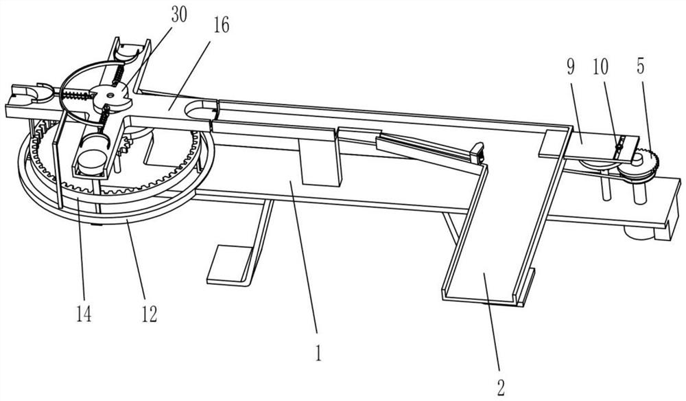
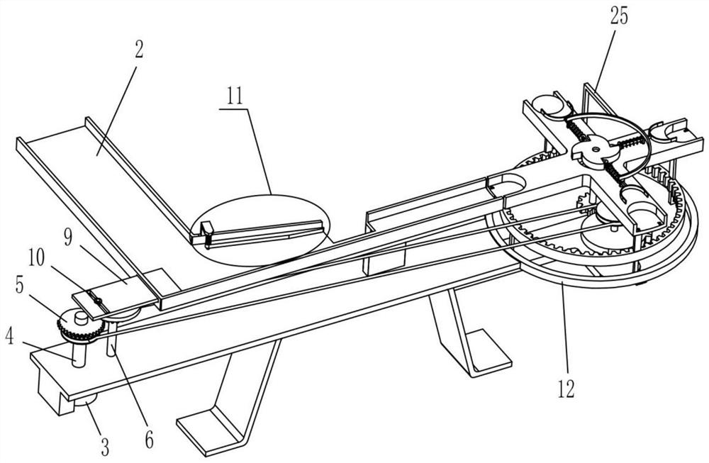
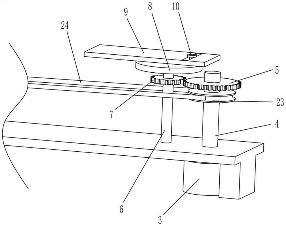
[0022] A bearing diameter detection and separation device, such as Figure 1-8 As shown, it includes a support 1, a slide plate 2, a motor 3, a rotating shaft 4, a first sector gear 5, a conversion shaft 6, a pinion 7, a turntable 8, a push plate 9, a pin rod 10, an annular slide rail 12, an annular Slide block 13, internal gear one 14, pole 15, rotating disk 16, transmission device and pushing device, described slide plate 2 is fixedly installed on the bearing 1, and described motor 3 is fixedly installed on the lower side of bearing 1 and motor 3 The output shaft passes through the support 1, the lower end of the rotating shaft 4 is connected to the output shaft of the motor 3, the first sector gear 5 is fixedly installed on the upper end of the rotating shaft 4, and the conversion shaft 6 is installed on the support through a bearing 1, the turntable 8 is fixedly installed on the upper end of the conversion shaft 6, the pinion 7 is fixedly installed on the conversion shaft ...

Embodiment 2

[0025] On the basis of Embodiment 1, such as Figure 1-8 As shown, the transmission device includes a support plate 17, a transmission shaft 18, a gear two 19, a rotating rod 20, a second sector gear 21, a first pulley 22, a second pulley 23 and a belt 24, and the support plate The right end of 17 is fixedly installed on the left side of the support 1, the lower end of the transmission shaft 18 is installed on the support plate 17 through a bearing, the second gear 19 is fixedly installed on the transmission shaft 18, and the lower end of the rotating rod 20 is installed on the support plate through a bearing. On the plate 17 and behind the transmission shaft 18, the first pulley 22 is fixedly installed on the upper end of the rotating rod 20, and the second sector gear 21 is fixedly installed on the rotating rod 20 and is mutually connected with the second gear 19 and the first internal gear 14. meshing, the second pulley 23 is fixedly installed on the rotating shaft 4 and in...


PUM


Abstract

The invention relates to the field of bearing size detection and separation, in particular to a bearing diameter size detection and separation device. The technical problem of the present invention is to provide a bearing diameter detection and separation device that can automatically detect and screen bearings with different diameters, improve the efficiency of bearing detection and screening, and ensure the correct effect of detection and screening. The technical embodiment of the present invention is: a bearing diameter detection and separation device, including a support, a slide plate, a motor, a rotating shaft, a first sector gear, a conversion shaft, a pinion, a turntable, a push plate, a pin, an annular slide Rails, ring sliders, etc., the slide plate is fixedly installed on the support. The present invention enables bearings of different diameters to be arranged and pushed sequentially by setting an oscillating device without manual arrangement, which reduces the labor intensity of workers, automatically pushes bearings of different diameters continuously, performs correct detection and separation, and improves the detection efficiency of bearings .

Description

technical field [0001] The invention relates to the field of bearing size detection and separation, in particular to a bearing diameter size detection and separation device. Background technique [0002] Bearings are an important part of contemporary mechanical equipment. Its main function is to support the mechanical rotating body, reduce the friction coefficient during its movement, and ensure its rotation accuracy. Due to the wide variety of bearings and the different diameters of various bearings, it is necessary to test and screen bearings of different diameters when selecting bearings. However, when manually testing and screening a large number of bearings with different diameters, the workload is large, the efficiency is low, and In the process of detection and screening, the detection and selection of bearings may be wrong. Therefore, it is urgent to develop a simple and easy-to-operate bearing that can automatically detect and screen bearings of different diameters...

Claims


Application Information

Patent Timeline
Patent Type & Authority Patents(China)
IPC IPC(8): B07B13/04B07B13/14B07B13/16
CPCB07B13/04B07B13/14B07B13/16
Inventor 谢学海
Owner 常州市钧达轴承有限公司
Why Eureka
Try Eureka