
Transmission shaft component stall self-locking mechanism applied to wind generating set

A technology for wind turbines and transmission shafts, which is applied in the control of wind turbines, wind turbines, and wind power generation, etc., can solve the problems of overloading the power of wind turbines, affecting the normal use of internal structures, and increasing the wear and tear of power generation devices, so as to eliminate safety issues. The effect of avoiding hidden dangers, avoiding equipment damage and increasing service life

Active Publication Date: 2020-08-28
国电崇礼和泰风能有限公司
View PDF4 Cites 13 Cited by
  • Summary
  • Abstract
  • Description
  • Claims
  • Application Information

AI Technical Summary

Problems solved by technology

However, if the speed is too fast, the power of the wind power generation equipment will be overloaded, which may lead to problems such as increased wear and tear of the power generation equipment and a shortened service life. High, affecting the normal use of the internal structure, causing equipment damage or even fire
When the speed exceeds the rated value too much, it will seriously cause the wind power generation equipment to collapse. For the equipment installed on the high place of the roof, there is a great potential safety hazard, which seriously threatens the safety of users.

Method used


Image

  • Transmission shaft component stall self-locking mechanism applied to wind generating set
  • Transmission shaft component stall self-locking mechanism applied to wind generating set
  • Transmission shaft component stall self-locking mechanism applied to wind generating set

Examples


Embodiment Construction

[0024] The following will clearly and completely describe the technical solutions in the embodiments of the present invention with reference to the accompanying drawings in the embodiments of the present invention. Obviously, the described embodiments are only some, not all, embodiments of the present invention. Based on the embodiments of the present invention, all other embodiments obtained by persons of ordinary skill in the art without making creative efforts belong to the protection scope of the present invention.

[0025] see Figure 1-6 :

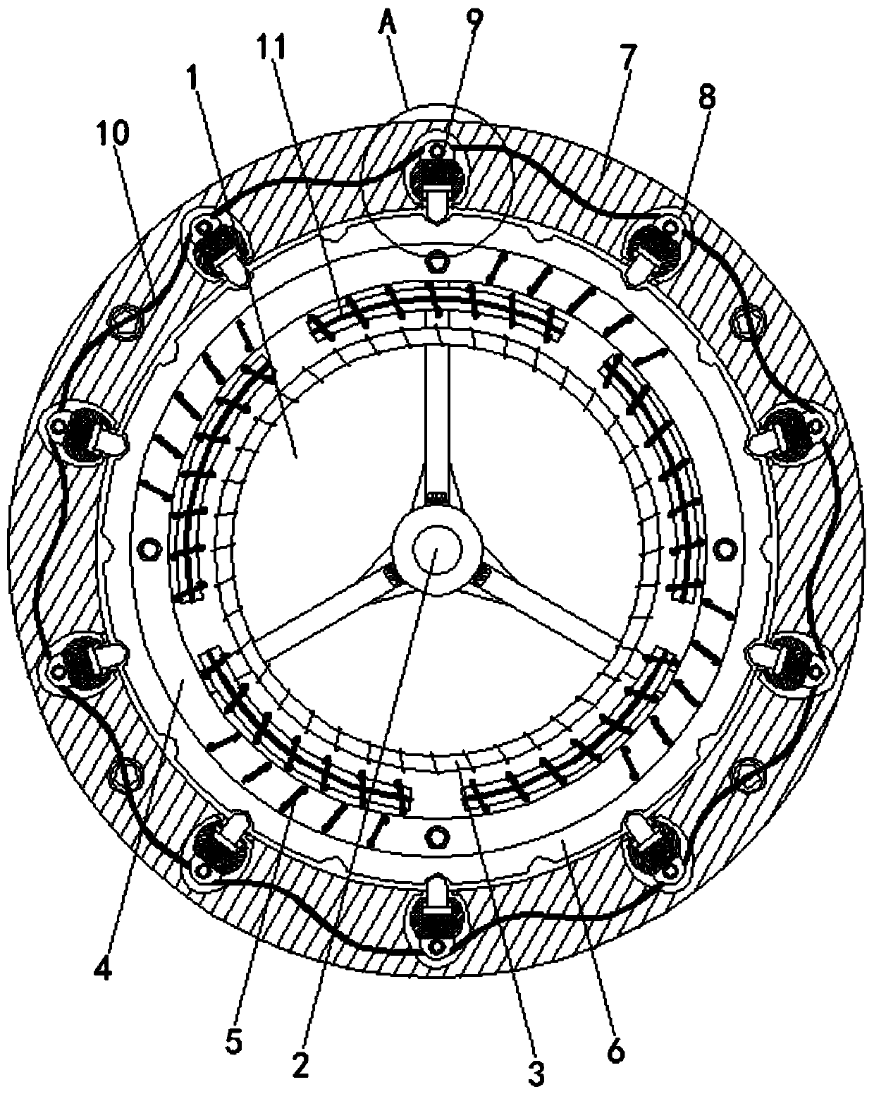
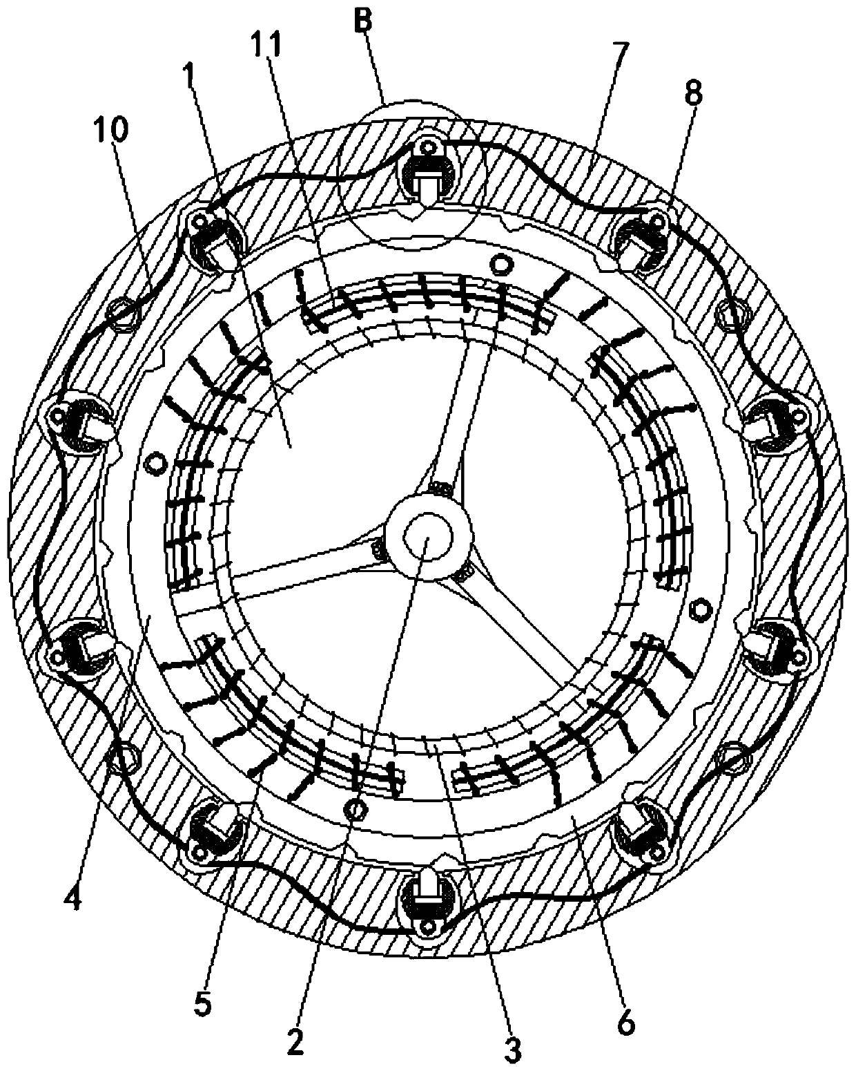
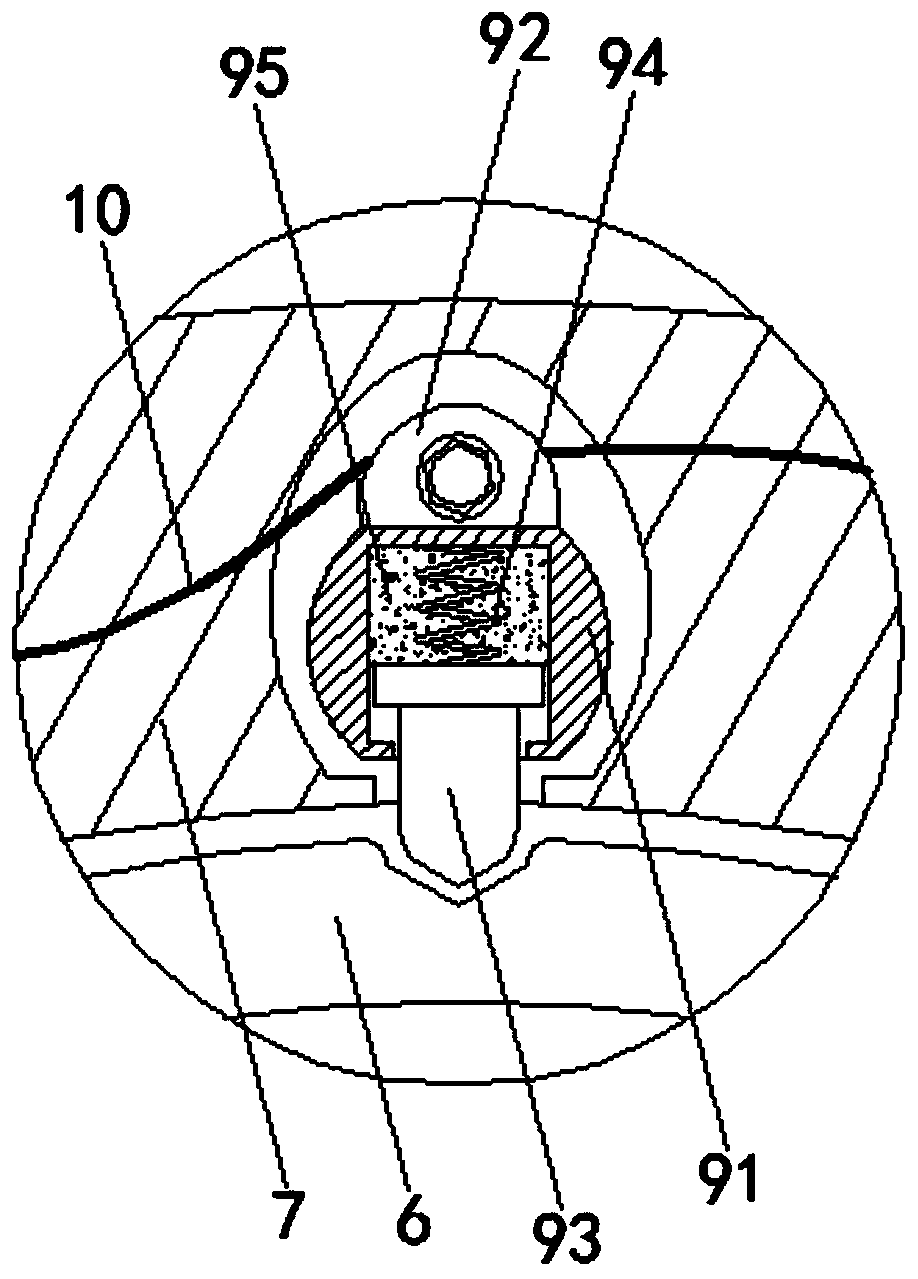
[0026] The stall self-locking mechanism of the transmission shaft component applied to the wind power generating set includes a mounting base plate 1, a transmission shaft 2, a main conductor 3, a positioning ring 4, a secondary conductor 5, a self-locking disc 6, a mounting ring 7, a cavity 8, and a self-locking mechanism. Lock mechanism 9 , wire 10 , coil 11 , encapsulation case 91 , conductive seat 92 , self-locking block 93 , re...


PUM


Abstract

The invention discloses a transmission shaft component stall self-locking mechanism applied to a wind generating set and relates to the technical field of new energy. The transmission shaft componentstall self-locking mechanism comprises an installation bottom plate. A transmission shaft is movably connected to the front face of the installation bottom plate. A main guide body is fixedly connected to the outer side of the transmission shaft. A positioning ring is fixedly connected to the outer side of the transmission shaft. An auxiliary guide body is arranged in the positioning ring. By means of the transmission shaft component stall self-locking mechanism applied to the wind generating set, the problem that the inner temperature is increased due to the stall of the wind generating set can be prevented, burnout of structures in the unit is avoided, and normal use of the equipment is ensured. Meanwhile, the fire breakout problem caused by the too high temperature of power generation equipment is eradicated fundamentally, and the use safety of the equipment is greatly ensured. In addition, safety of an installation user can be improved, the problem of equipment collapse possibly caused by the too high rotating speed is prevented, equipment burnout is avoided, potential safety hazards are also eliminated, and the transmission shaft component stall self-locking mechanism better meets practical use requirements.

Description

technical field [0001] The invention relates to the field of new energy technology, in particular to a stall self-locking mechanism for a drive shaft component applied to a wind power generating set. Background technique [0002] As a kind of new energy, wind power generation occupies a certain market in the field of new energy due to its advantages of cleanness, high efficiency and low cost. Generally speaking, wind power generation can be divided into wind power plants and small household wind power generation equipment. The two methods have the same power generation principle, and generally there is no major difference in structure. [0003] For domestic wind power generation equipment, due to the consideration of power generation efficiency, it is often chosen to be installed on a high roof or in an open courtyard, so that it can be driven by the wind at the greatest angle. The existing principle of wind power generation can be simply understood as the wind drives the o...

Claims


Application Information

Patent Timeline
IPC IPC(8): F03D7/04
CPCF03D7/0256Y02E10/72
Inventor 赵群燕
Owner 国电崇礼和泰风能有限公司
Learn More