
Slider structure and injection mold

A technology of sliders and slider seats, which is applied in the direction of transmission devices, belts/chains/gears, mechanical equipment, etc., and can solve problems such as core pulling of difficult workpieces

Active Publication Date: 2020-08-25
SHENZHENSHI YUZHAN PRECISION TECH CO LTD
View PDF3 Cites 0 Cited by
  • Summary
  • Abstract
  • Description
  • Claims
  • Application Information

AI Technical Summary

Problems solved by technology

The current solution to this problem is to use multiple slider seats to cooperate with the core-pulling inserts. However, in order to have enough space for arranging multiple slider seats, the core-pulling inserts must be elongated, but the core-pulling inserts must be elongated. If the core structure is too long, it cannot be easily inserted into the workpiece, and it is also difficult to pull the core out of the workpiece

Method used


Image

  • Slider structure and injection mold
  • Slider structure and injection mold
  • Slider structure and injection mold

Examples


Embodiment Construction

[0095] The following will clearly and completely describe the technical solutions in the embodiments of the present invention with reference to the accompanying drawings in the embodiments of the present invention. Obviously, the described embodiments are only some, not all, embodiments of the present invention. Based on the embodiments of the present invention, all other embodiments obtained by persons of ordinary skill in the art without making creative efforts belong to the protection scope of the present invention.

[0096] It should be noted that when a component is considered to be "connected" to another component, it may be directly connected to the other component or there may be an intervening component at the same time. When a component is said to be "set on" another component, it can be set directly on the other component or there may be an intervening component at the same time. The terms "top", "bottom", "upper", "lower", "left", "right", "front", "rear", and simi...


PUM


Abstract

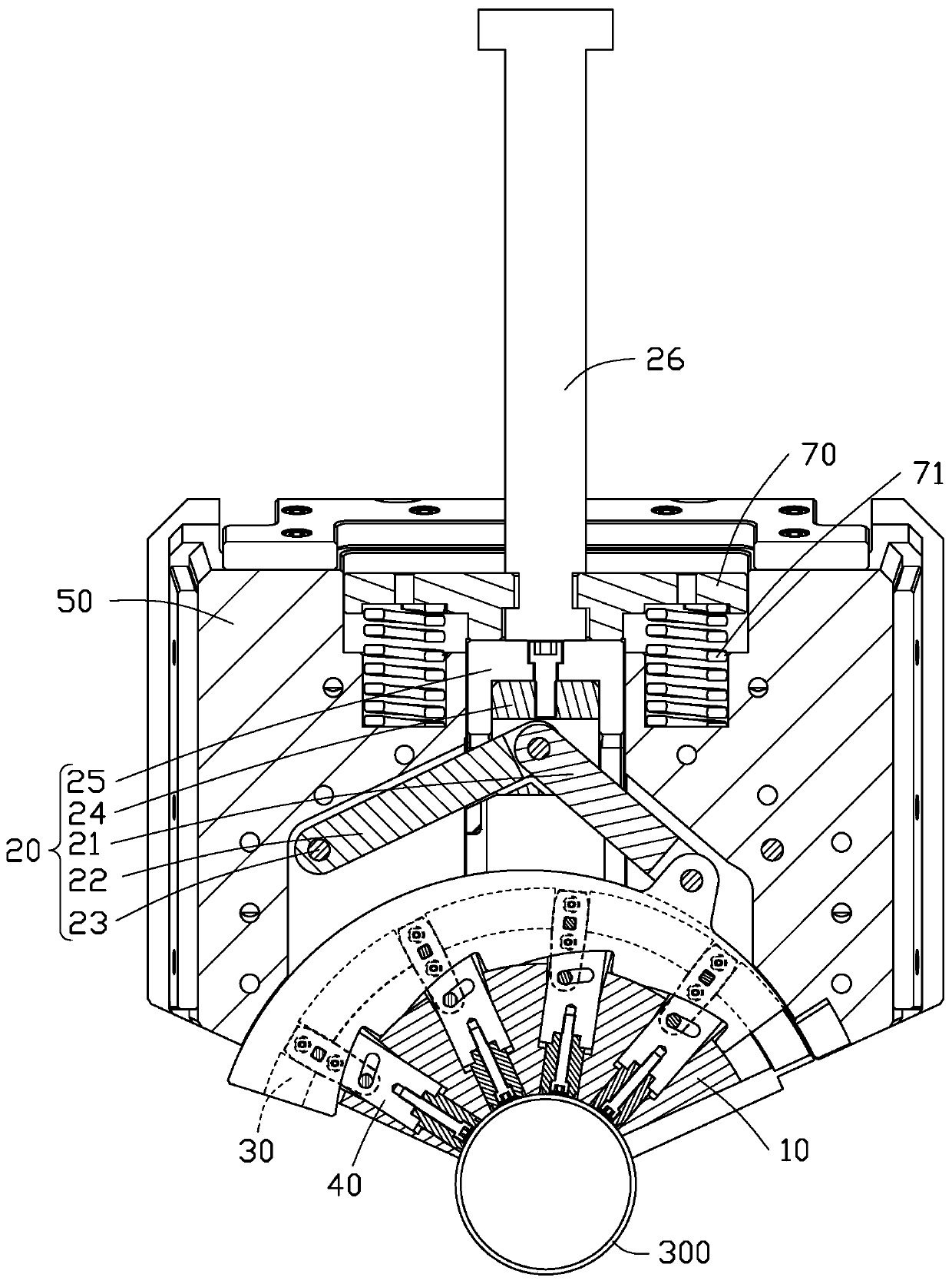
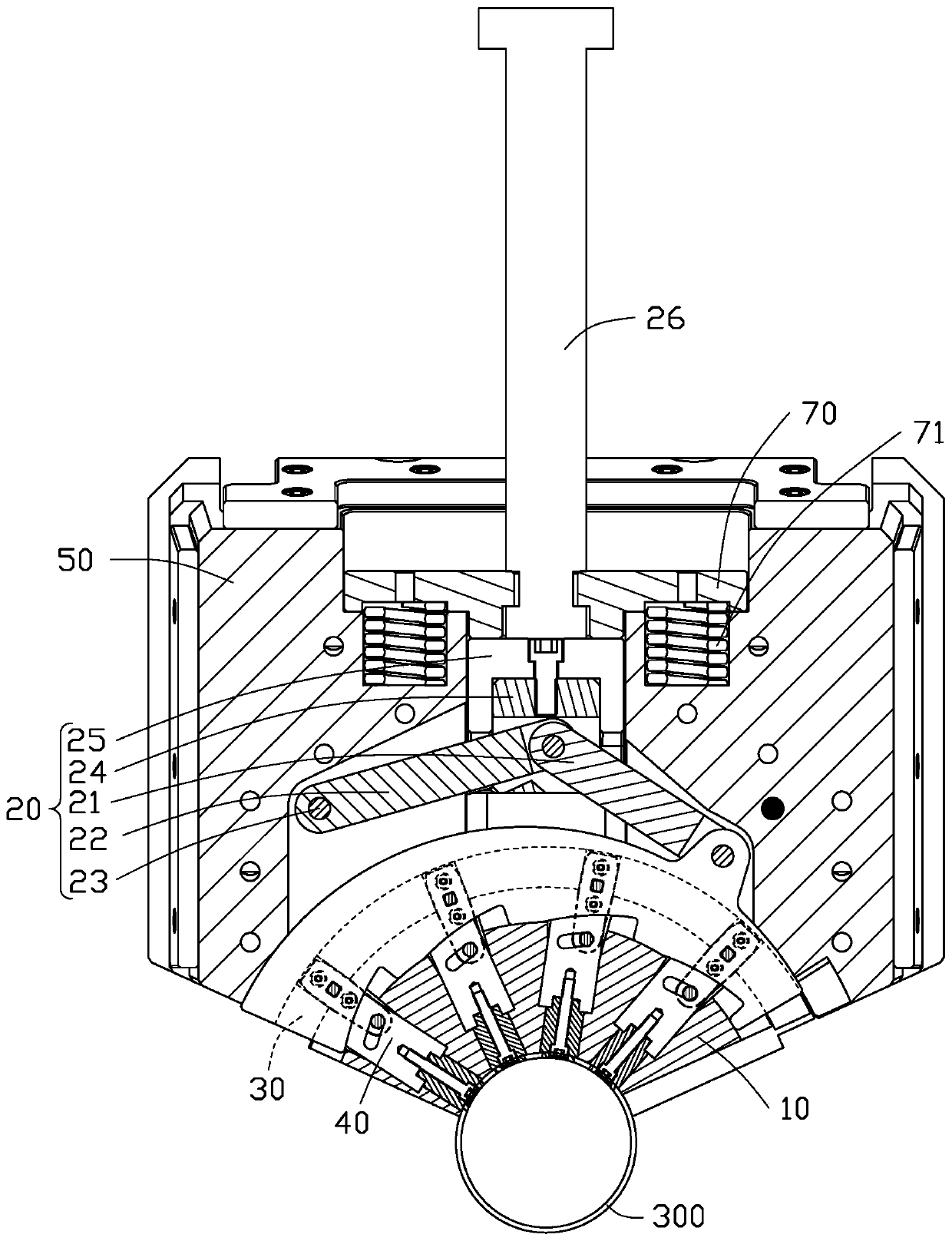
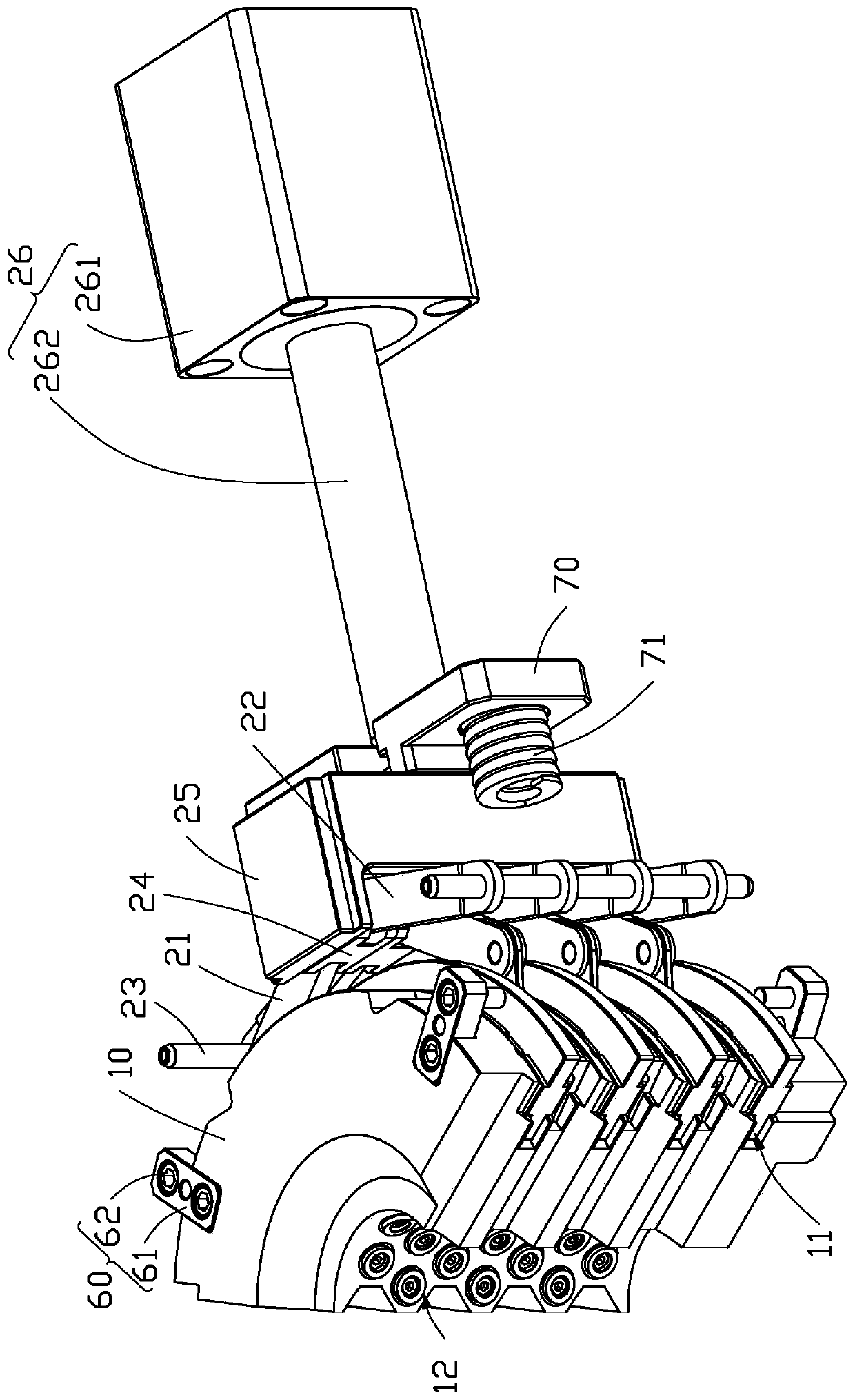
The invention provides a slider structure. The slider structure is used for clamping or inserting a workpiece and comprises a connecting rod assembly, at least one rotating assembly, a guide base andat least one functional assembly. The connecting rod assembly is connected with the rotating assembly; one rotating assembly is connected with at least one functional assembly; and the rotating assembly and the functional assembly are both slidably connected with the guide base. Under the driving of a power source, the connecting rod assembly drives the rotating assembly to rotate on the guide base, and the rotating assembly drives the functional assembly to slide along the guide base so that the functional assembly is clamped or inserted into the workpiece. The invention also relates to an injection mold adopting the above-mentioned slider structure; by using the slider structure, the power source drives the rotating assembly to rotate after driving the connecting rod assembly to move, sothat the functional assembly is further moved in the guide base, and the functional assembly is clamped or inserted into the workpiece so as to realize more convenient operation, and meanwhile the efficiency for processing the workpiece is improved.

Description

technical field [0001] The invention relates to the field of mold technology, in particular to a slider structure and an injection mold Background technique [0002] Due to the needs of assembly or actual use of existing workpieces, a plurality of circular holes will be provided on the workpieces when forming the workpieces. For example, for some parts on audio products, multi-layer round holes need to be opened because the audio diffuses the sound. The current solution to this problem is to use multiple slider seats to cooperate with the core puller, but in order to have enough space to arrange multiple slider seats, the core puller must be elongated, but the pullout of the core puller If the core structure is too long, it cannot be easily inserted into the workpiece, and it is also difficult to pull the core out of the workpiece. Contents of the invention [0003] In view of this, it is necessary to provide a slider structure and an injection mold, which can be more co...

Claims


Application Information

Patent Timeline
Patent Type & Authority Applications(China)
IPC IPC(8): B29C45/33B29C45/40B29C45/17F16H37/12
CPCB29C45/332B29C45/4005B29C45/1769F16H37/122
Inventor 张友学
Owner SHENZHENSHI YUZHAN PRECISION TECH CO LTD
Learn More