Flow Optimized Vane Pumps

A vane pump and vane technology, applied in the field of flow-optimized vane pumps, can solve problems affecting the volumetric efficiency of the pump, achieve the effects of suppressing the decline in volumetric efficiency, reducing the generation of high-pressure peaks, and preventing hydraulic short circuits

Active Publication Date: 2021-12-14
尼得科GPM有限公司
View PDF1 Cites 0 Cited by
  • Summary
  • Abstract
  • Description
  • Claims
  • Application Information

AI Technical Summary

Problems solved by technology

This change in pump geometry leads to an open transition of the vane chamber between feed and discharge in each working stroke, which can adversely affect the volumetric efficiency of the pump

Method used


Image

  • Flow Optimized Vane Pumps
  • Flow Optimized Vane Pumps
  • Flow Optimized Vane Pumps

Examples


Embodiment Construction

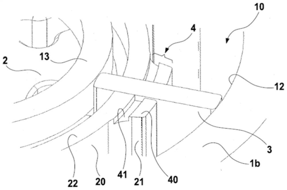
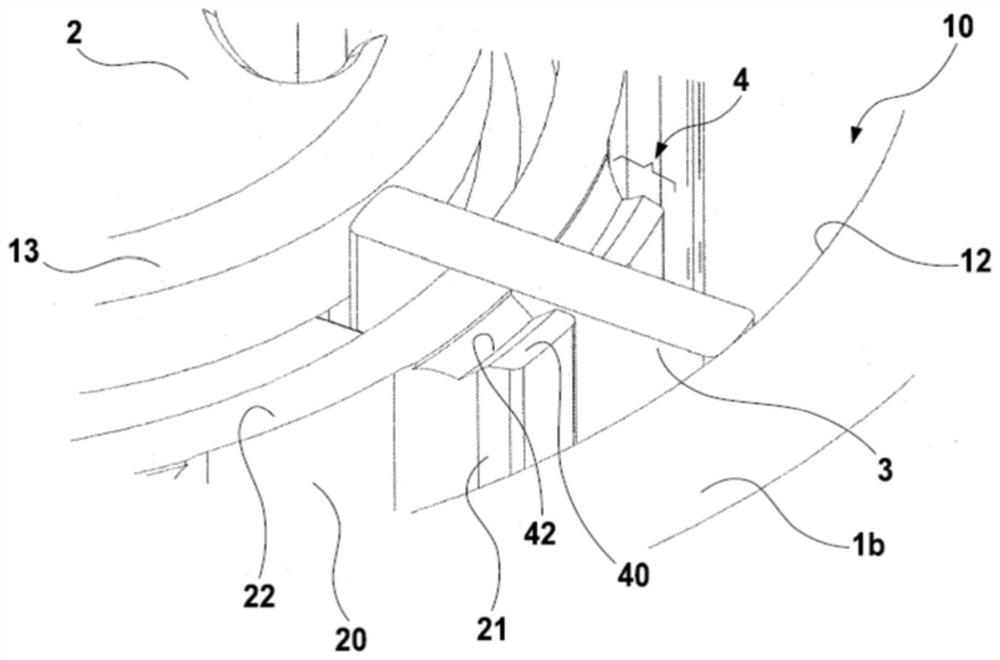
[0031] will be referred to below Figure 1 to Figure 3 The structure of the vane pump according to the present invention will be described.

[0032] figure 1 Shows a view of an open pump housing 1 of a variable volume vane pump from which the pump cover has been removed. In order to be able to set the delivered volumetric flow independently of the rotational speed of the pump, the pump has a variable pump geometry that is adjusted with the displacement between the two housing parts.

[0033] The housing part 1a constitutes the main part of the pump housing 1 and houses the inlet 5, the outlet 6 and the actuator 7 with the return spring 70 therein. Furthermore, the rotor 2 is rotatably mounted in the housing part 1a, whereby the rotor 2 and the housing part 1a define fixed parts with respect to the adjustment movement of the variable pump geometry. The lifting ring 1b comprising the pump chamber 10 is housed in the outer shell part 1a in a displaceable manner together with t...


PUM


Abstract

The invention relates to a vane pump for conveying liquid (especially viscous oil), comprising: a rotor (2) having a sliding groove (23) in which a slidable vane (3) is accommodated and which can be moved relative to the radius of the rotor ( r) indentation; the pump housing (1) with the pump chamber (10) housing the rotor (2); and the inlet (5) and outlet (6) towards at least The end side of the rotor (2) is open into the pump chamber (10); wherein around the circumference of the rotor (2) radial elevations (21) protruding towards the sliding slots (23) form the recesses to the retractable vanes (3) The rotor radius (r) on either side, and at the radially raised portion (21), the radially recessed portion (20) is recessed relative to the rotor radius (r). In the radial elevation (21), on at least one end side of the rotor (2) to which the inlet (5) and the outlet (6) are open, a recess (4) is formed which provides a Rotary servo control geometry for pressure peaks in the small vane chamber.

Description

technical field [0001] The invention relates to a flow-optimized vane pump with reduced pressure pulsations in the vane chamber. Background technique [0002] In contrast to centrifugal pumps, rotary positive displacement pumps, such as vane pumps, in principle suffer pressure pulsations which arise during one revolution of the pump shaft from the sequence of the feed and discharge cycles. This pulsation is related to the initial pressure of the pump during load changes and flow characteristics of the flow being delivered from the inlet into the vane chamber and from the vane chamber to the outlet, and also to the internal pressure of the simultaneously closed vanes. In general, pulsating pressures in confined spaces or circuits of hydraulic systems cause problems such as reduced durability of sealing points or generation of noise with perceivable resonance. [0003] The prior art discloses vane pumps with different specific geometries aimed at reducing pulsation. For exam...

Claims


Application Information

Patent Timeline
Patent Type & Authority Patents(China)
IPC IPC(8): F04C2/344F04C14/22F04C15/00
CPCF04C2/3442F04C14/223F04C15/0049F04C2240/20F04C2270/145F04C2210/206F04C2240/30
Inventor 塞巴斯蒂安·西德尔
Owner 尼得科GPM有限公司
Why Eureka
Try Eureka