
Wind generating set and cable transition device

A cable and package technology, which is applied in the direction of wind turbines, wind power generation, electromechanical devices, etc., can solve the problems affecting the installation and layout of other equipment, difficult cable spacing and heat dissipation requirements, and occupying the inner space of the tower, so as to increase the cable laying space , Solve the heat dissipation problem, compress the effect of installation space

Pending Publication Date: 2020-08-11
SANY ELECTRIC CO LTD
View PDF0 Cites 1 Cited by
  • Summary
  • Abstract
  • Description
  • Claims
  • Application Information

AI Technical Summary

Problems solved by technology

[0005] Most of the traditional cable transition devices adopt a cylindrical stacking structure, and with the increase of fan power, the number of cables can be as many as 30, and the cylindrical stacking structure is difficult to meet the cable spacing and heat dissipation requirements, unless it is greatly increased Structural size, but it will take up a lot of internal space of the tower and affect the installation and layout of other equipment
[0006] Cable transition devices with other structures are also provided in the prior art, but most of them have problems such as high cost, inconvenient installation, large space occupation, and poor heat dissipation effect.

Method used


Image

  • Wind generating set and cable transition device
  • Wind generating set and cable transition device
  • Wind generating set and cable transition device

Examples


Embodiment Construction

[0027] It should be noted that, in the case of no conflict, the embodiments of the present invention and the features in the embodiments can be combined with each other. The present invention will be described in detail below with reference to the accompanying drawings and examples.

[0028] In the description of the present invention, it should be noted that unless otherwise specified and limited, the terms "installation", "connection" and "connection" should be understood in a broad sense, for example, it can be a fixed connection or a detachable connection. Connection, or integral connection, may also be mechanical connection, direct connection, or indirect connection through an intermediary, or internal communication between two elements. Those of ordinary skill in the art can understand the specific meanings of the above terms in the present invention in specific situations.

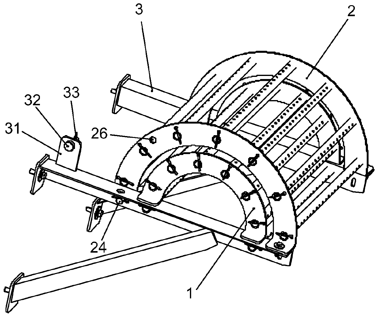
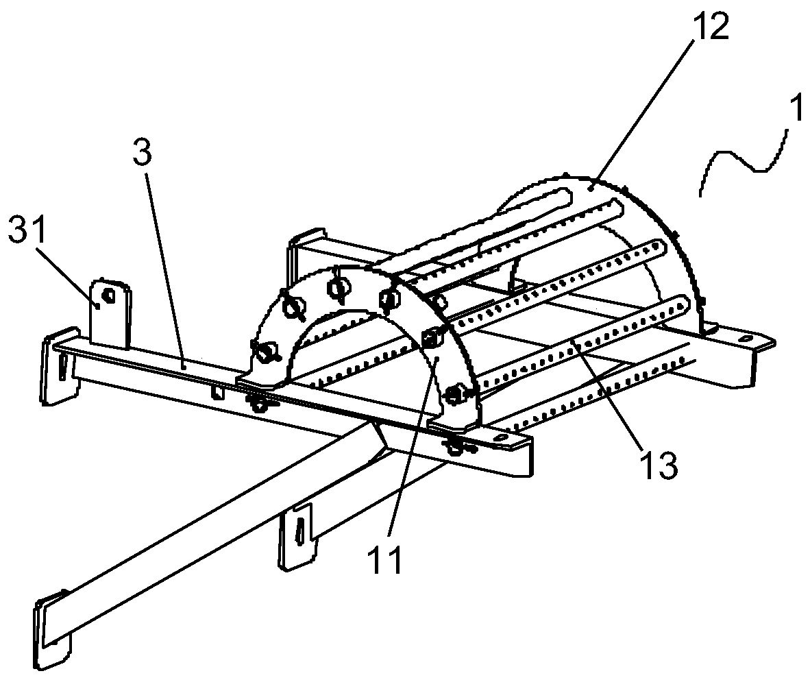
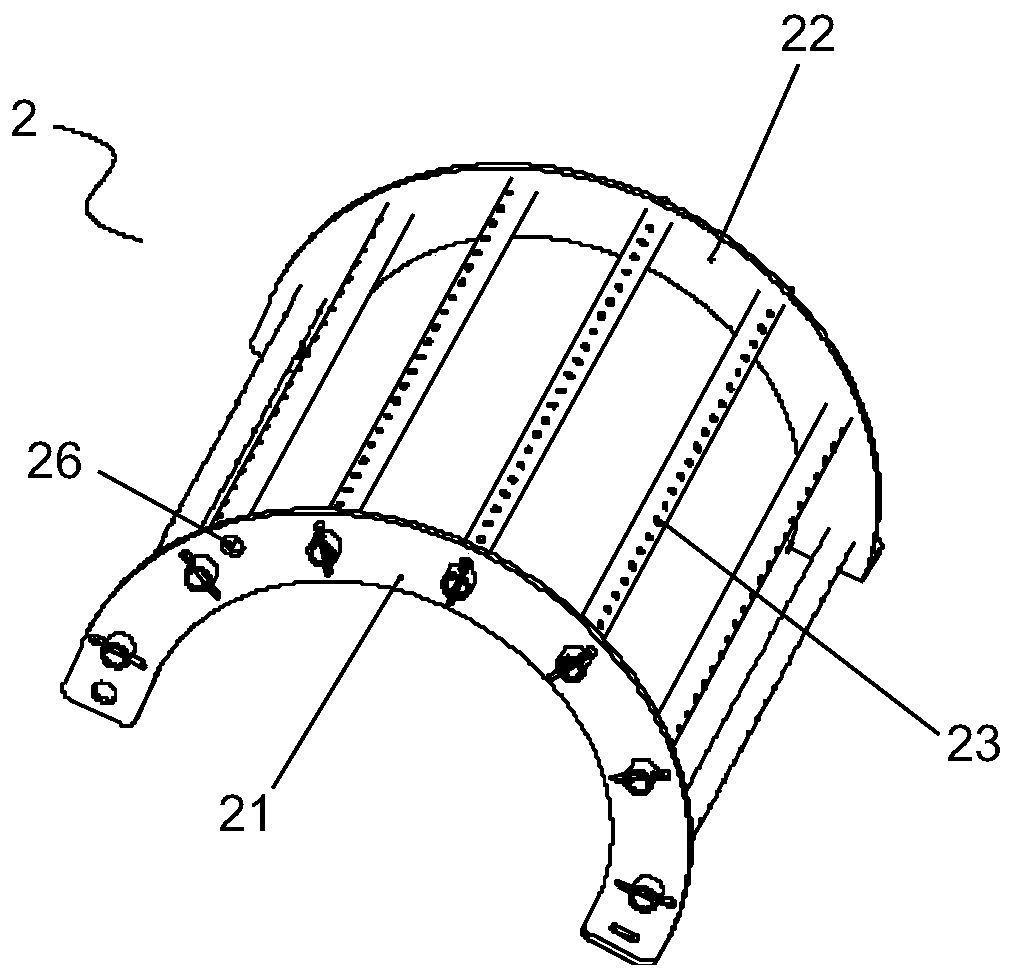
[0029] Such as figure 1 As shown, the cable transition device of this embodiment includes a fi...


PUM


Abstract

The invention discloses a cable transition device, which comprises a mounting seat and at least two layers of saddle supports, the at least two layers of saddle supports are sleeved on the mounting seat layer by layer, and the saddle support arranged on the outer layer can be opened relative to the saddle support arranged on the inner layer and is used for reserving a cable laying operation spacefor the saddle support arranged on the inner layer. By arranging at least two layers of saddle supports, the cable laying space is greatly enlarged, the spacing requirement of cable laying can be wellmet, the current-carrying capacity of the cable is improved, the heat dissipation problem of the cable is synchronously solved, the current-carrying capacity of the cable is further improved, and theservice life of the cable is further prolonged. Besides, the saddle supports are installed in a layer-by-layer sleeving mode, the installation occupied space is further reduced, the outer-layer saddle support can be opened relative to the inner-layer saddle support, the structure is easy to achieve, and cable laying operation is convenient.

Description

technical field [0001] The invention relates to the technical field of wind power generating equipment, in particular to a wind power generating set and a cable transition device. Background technique [0002] A wind turbine is a device that converts wind energy into electrical energy, obtains wind power through blades, and transmits torque to a generator for power generation. The blades and generators are installed on the top of the tall tower, and the electrical equipment used to control the operation of the blades and generators is usually installed at the bottom of the tower, so the cables connecting the blades, generators and electrical equipment need to pass through the nacelle along the height of the tower to lay. [0003] With the gradual increase of the capacity of a single wind turbine unit, the cable is required to transmit more electric energy, that is, the cable is required to have a larger ampacity and can pass a larger current. The ampacity of the cable is cl...

Claims


Application Information

Patent Timeline
Patent Type & Authority Applications(China)
IPC IPC(8): H02G3/02H02G3/04H02K5/22F03D80/80F03D80/00
CPCF03D80/00F03D80/85H02G3/02H02G3/0456H02K5/225Y02E10/72
Inventor 曾洁如易权胡柱
Owner SANY ELECTRIC CO LTD
Learn More