
Lane-level positioning method and system, computer equipment, vehicle and storage medium

A positioning method and lane-level technology, which are applied to lane-level positioning during vehicle driving, computer equipment, vehicles, and storage media fields, can solve the problems of less consideration, high cost, and high cost of lidar, and can support mass production, cost reduction effect

Active Publication Date: 2020-08-07
GUANGZHOU AUTOMOBILE GROUP CO LTD
View PDF2 Cites 15 Cited by
  • Summary
  • Abstract
  • Description
  • Claims
  • Application Information

AI Technical Summary

Problems solved by technology

Due to the large error of the traditional GPS positioning technology, it cannot meet the high-precision positioning requirements, so the lane-level positioning system for autonomous vehicles came into being
[0003] For now, there are many lane-level positioning system solutions for autonomous vehicles, most of which focus on the development of a single technology, but less consideration is given to the needs of supporting mass production, high reliability and low cost
For example, high-precision positioning differential services and high-cost inertial navigation. This high-precision absolute positioning solution is currently costly and cannot be applied to mass-produced autonomous vehicles in a short time; another example is multi-beam laser radar and high-precision map self-positioning solutions. The cost of lidar is too high to be applied in mass-produced self-driving vehicles in a short time
[0004] In summary, the existing lane-level positioning technology for autonomous vehicles still needs to be further improved.

Method used


Image

  • Lane-level positioning method and system, computer equipment, vehicle and storage medium
  • Lane-level positioning method and system, computer equipment, vehicle and storage medium
  • Lane-level positioning method and system, computer equipment, vehicle and storage medium

Examples


Embodiment Construction

[0082] Various exemplary embodiments, features, and aspects of the present disclosure will be described in detail below with reference to the accompanying drawings. The same reference numbers in the figures indicate functionally identical or similar elements. While various aspects of the embodiments are shown in drawings, the drawings are not necessarily drawn to scale unless specifically indicated.

[0083] In addition, in order to better illustrate the present invention, numerous specific details are given in the following specific examples. It will be understood by those skilled in the art that the present invention may be practiced without certain of the specific details. In some instances, means well known to those skilled in the art are not described in detail in order to highlight the gist of the present invention.

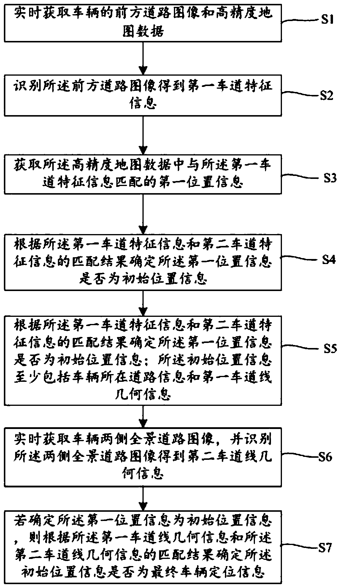
[0084] Such as figure 1 As shown, Embodiment 1 of the present invention provides a lane-level positioning method for an automatic driving vehicle, incl...


PUM


Abstract

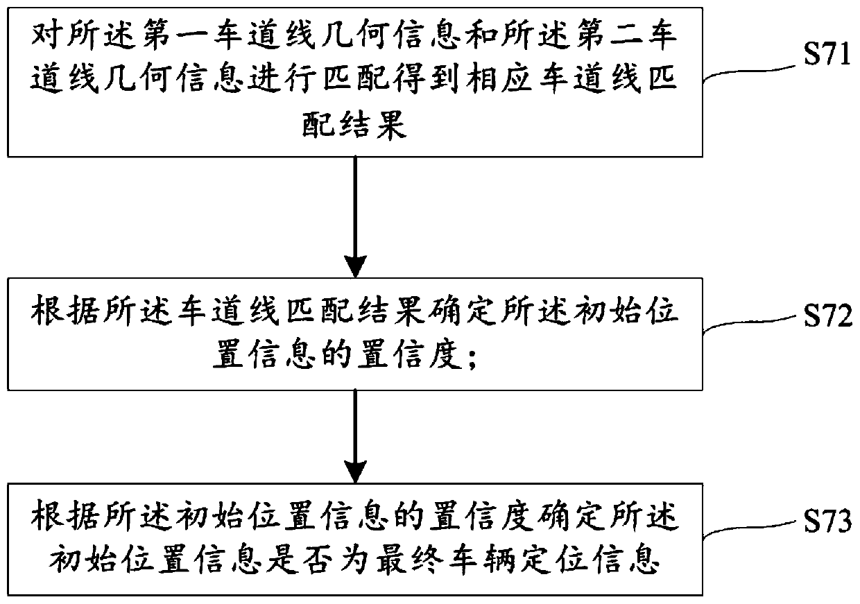
The invention relates to a lane-level positioning method and system, computer equipment, a vehicle and a storage medium. The method comprises the following steps: acquiring a front road image, absolute position information and high-precision map data of the vehicle; identifying the front road image to obtain first lane feature information; determining initial positioning information of the vehicleaccording to the first lane feature information, the absolute position information and the high-precision map data; obtaining panoramic road images on the two sides of the vehicle, and recognizing the panoramic road images on the two sides to obtain second lane line geometrical information; and matching the first lane line geometrical information with the second lane line geometrical informationto obtain a lane line matching result, and determining whether the initial positioning information is final vehicle positioning information or not according to the lane line matching result. The system, the computer equipment and the storage medium are carriers for implementing the method, and the vehicle comprises the system and the computer equipment. The method and the system can improve the positioning reliability of the automatic driving lane level.

Description

technical field [0001] The invention relates to the technical field of vehicle positioning in the process of automatic driving, in particular to a lane-level positioning method and system, computer equipment, vehicles, and storage media in the process of vehicle driving. Background technique [0002] As the number of cars continues to increase, road safety issues become more prominent and cannot be ignored. Therefore, advanced driver assistance systems have become a research hotspot. Due to the large error of the traditional GPS positioning technology, it cannot meet the high-precision positioning requirements, so the lane-level positioning system for autonomous vehicles came into being. [0003] For now, there are many lane-level positioning system solutions for autonomous vehicles, most of which focus on the development of a single technology, but less consideration is given to supporting mass production, high reliability, and low cost. For example, high-precision positio...

Claims


Application Information

Patent Timeline
Patent Type & Authority Applications(China)
IPC IPC(8): G06K9/00G06F16/29
CPCG06V20/588Y02T10/40
Inventor 王祥张芬黄亮郭继舜
Owner GUANGZHOU AUTOMOBILE GROUP CO LTD
Learn More