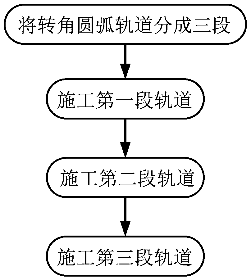
Corner arc track arrangement process
A circular arc track and track technology, which is applied in the field of corner circular arc track layout technology, can solve the problems of inability to use large cranes for installation, inability to approach bridges and turn construction, etc.
- Summary
- Abstract
- Description
- Claims
- Application Information
AI Technical Summary
Problems solved by technology
Method used
Image


Examples
Embodiment 1
[0044] This embodiment discloses the structure of the corner arc track.
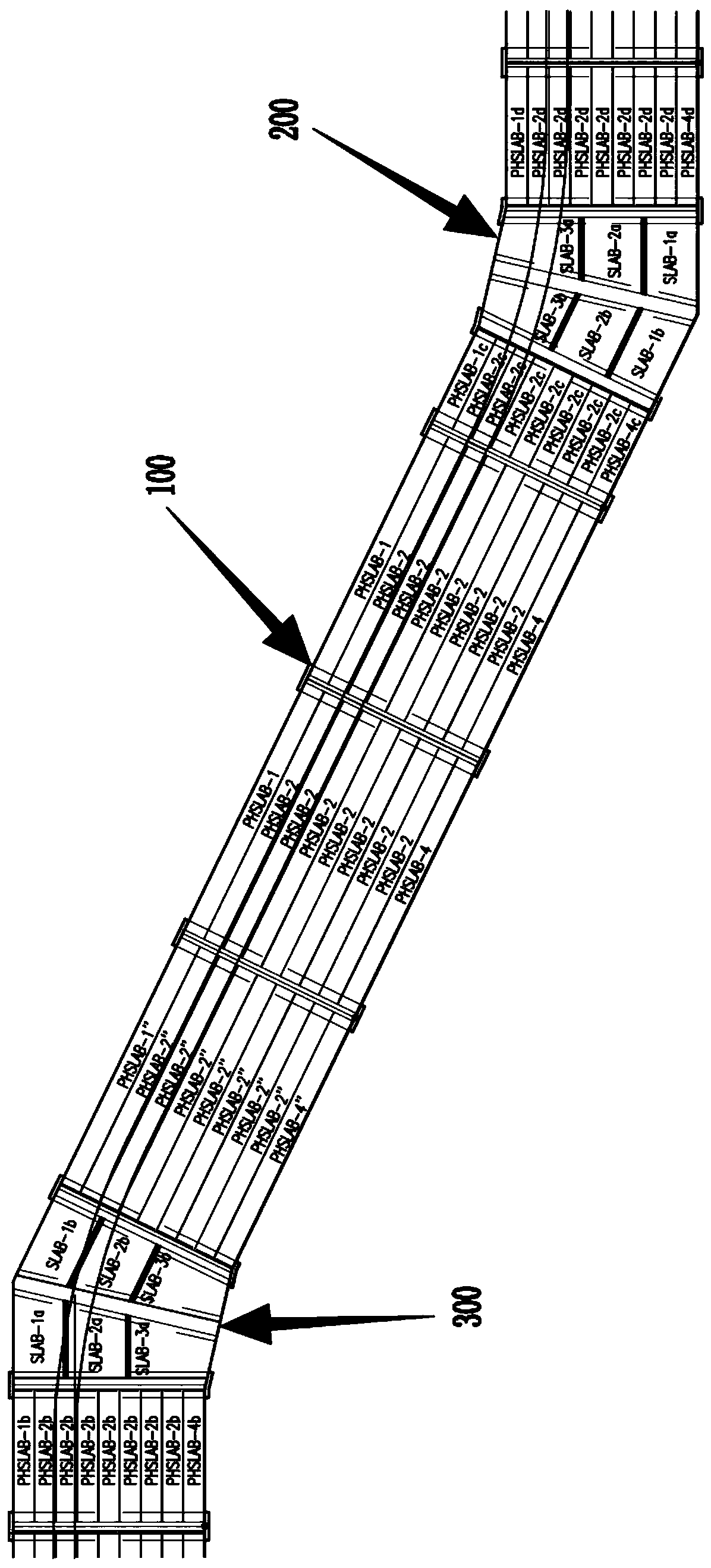
[0045] Such as Figure 2 to Figure 4 As shown, the structure of the corner arc track includes first to third prestressed hollow slab groups 330 and first to fourth prefabricated special-shaped solid slab groups 320; wherein, the first prefabricated special-shaped solid slab group 210 and the second prefabricated special-shaped solid The plate group 220 is spliced along the broken line path of the approach bridge 100, the first prestressed hollow plate group 230 is spliced with the first prefabricated special-shaped solid plate group 210 along the broken line path of the approach bridge 100, and the second prestressed hollow plate group 240 is spliced along the broken line path of the approach bridge 100 splicing with the second prefabricated special-shaped solid plate group 220; side, the first to second prefabricated special-shaped solid slab groups 220 and the first to second prestressed hollow ...
Embodiment 2
[0056] This embodiment discloses the steel platform structure of the present invention.
[0057] Such as Figure 6 to Figure 9 As shown, it includes the lower main beam 1 and the upper distribution beam 3, a plurality of auxiliary piles 2 are fixed under the lower main beam 1, the lower main beam 1 is fixed on the auxiliary piles 2, and the upper distribution beam 3 is fixed on the lower main beam. The upper beam 1; the lower main beam 1 is welded into a trapezoidal shape by multiple H-shaped steels and several first channel steels 12, the H-shaped steels are welded around the first channel steels 12, and the two ends of several first channel steels 12 are respectively connected to different H Shaped steel, several first channel steels 12 weld multiple H-shaped steels into one, and some first channel steels 12 are fixedly connected with auxiliary piles 2; The channel steel 21 is welded into a trapezoidal shape, and several second channel steels 21 are distributed perpendicula...
Embodiment 3
[0062] On the basis of the solution disclosed in Embodiment 2, this embodiment discloses the process of turning the bridge erecting machine from the first turning angle 200 to the second turning angle 300 .
[0063] The bridge erecting machine of the present embodiment preferably utilizes 100 sides of the 13.5m wide approach bridge to allow the bridge erecting machine to realize its own steering in a non-working state.
[0064] The steering steps of the bridge erecting machine are:
[0065] (1) Use 120 wooden squares of 60cm×15cm×15cm as the protective layer (one layer) for the traversing track of the supporting legs and rear supporting legs in the bridge erecting machine to avoid direct contact between the traversing track and the top surface of the prestressed hollow slab.
[0066] (2) Use [32b channel steel temporary welding to widen the width of the middle support and rear support traverse track, and increase the contact area.
[0067] (3) Arrange 2 rails on the wooden si...
PUM
 Abstract
Description
Claims
Application Information
 - R&D
- Intellectual Property
- Life Sciences
- Materials
- Tech Scout
- Unparalleled Data Quality
- Higher Quality Content
- 60% Fewer Hallucinations
Browse by: Latest US Patents, China's latest patents, Technical Efficacy Thesaurus, Application Domain, Technology Topic, Popular Technical Reports.
© 2025 PatSnap. All rights reserved.Legal|Privacy policy|Modern Slavery Act Transparency Statement|Sitemap|About US| Contact US: help@patsnap.com