
Siphon oil discharging device and method for oil tank truck

A technology of oil tanker and siphon, applied in the direction of distribution device, special distribution device, liquid distribution, transportation or transfer device, etc. It can solve the problems of long working time, oil leakage, complicated process of disassembling and assembling pipelines, etc., and achieves convenience for personnel Effects of operation and speeding up the working time

Active Publication Date: 2020-08-07
军事科学院系统工程研究院军事新能源技术研究所
View PDF10 Cites 2 Cited by
  • Summary
  • Abstract
  • Description
  • Claims
  • Application Information

AI Technical Summary

Problems solved by technology

[0002] According to the requirements of loading and unloading operations, railway oil tank cars usually need to enter a special operation line for loading and unloading operations. However, for emergency emergency safety incidents, such as oil tank car fires, rail failures, etc., it is necessary to carry out emergency oil unloading in the field as an emergency unloading method , it is usually necessary to insert the oil suction pipe through the top one by one of the oil tanks one by one, and then connect the long pipeline to the oil delivery pump to carry out sequential operations. The operation time is long, the process of disassembling and assembling the pipeline is complicated and it is easy to cause oil leakage along the way

Method used


Image

  • Siphon oil discharging device and method for oil tank truck
  • Siphon oil discharging device and method for oil tank truck
  • Siphon oil discharging device and method for oil tank truck

Examples


Embodiment Construction

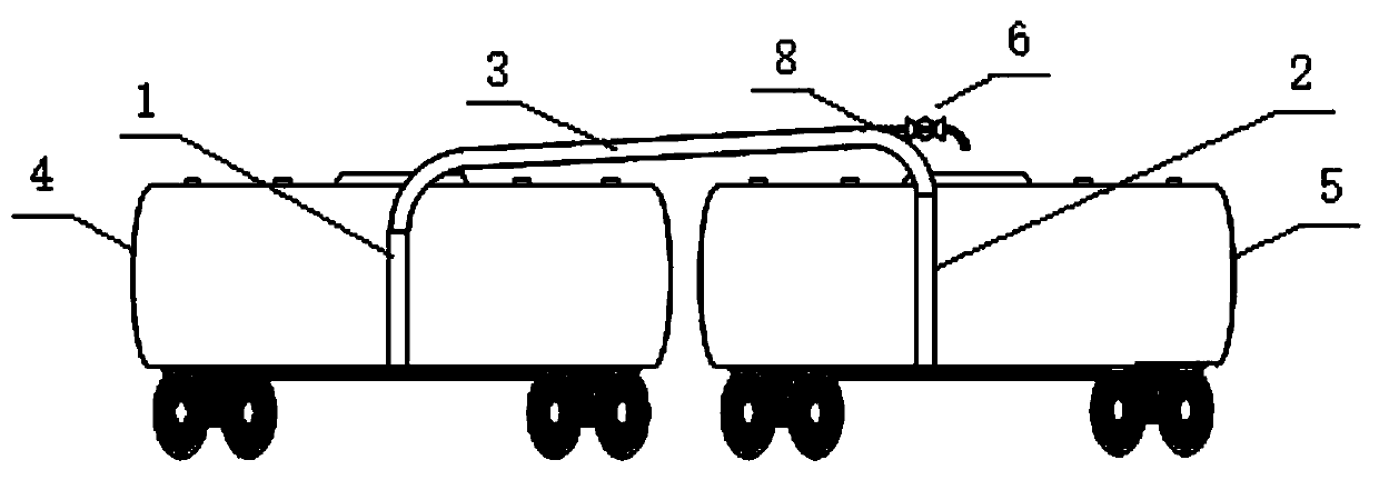
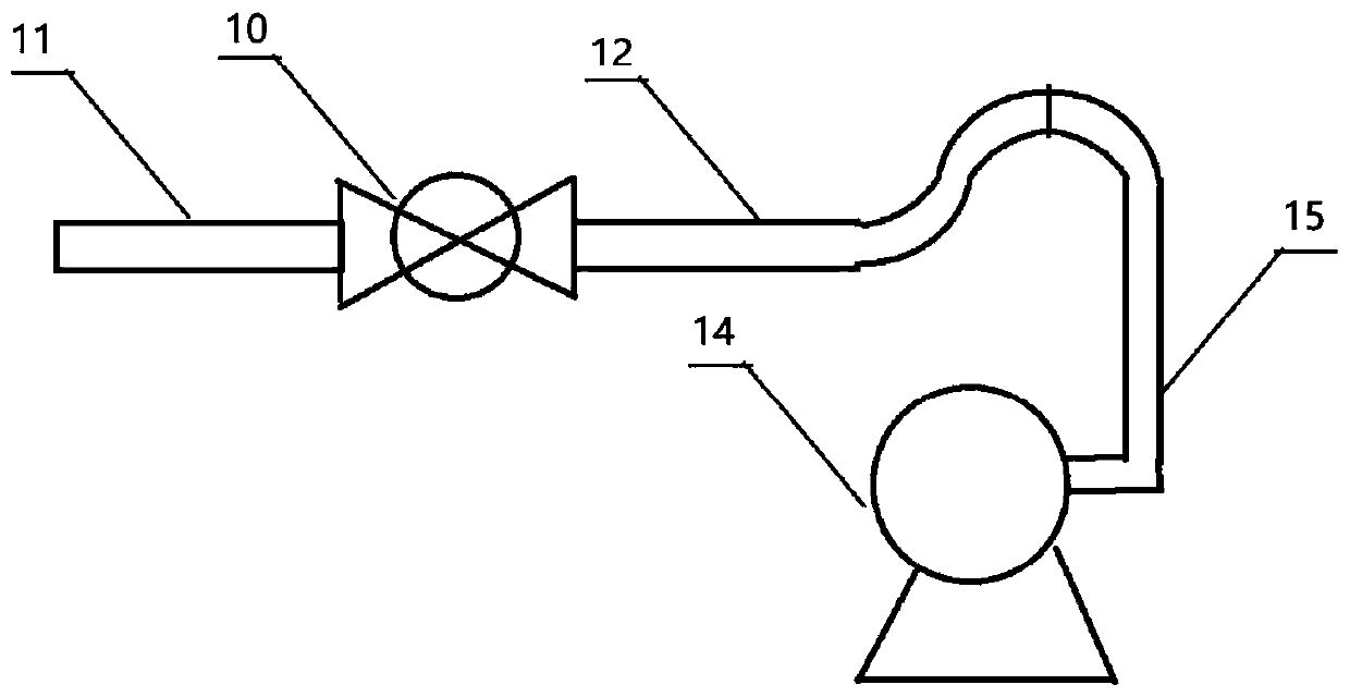
[0024] Such as Figure 1-2 As shown, the tank car siphon oil unloading device of the present invention generally includes a main oil unloading joint 2, one end of the main unloading oil joint 2 extends into the main unloading tank car 4; One end of the oil connection pipe extends into the secondary oil unloading tank car 5; a connecting pipe 3, the two ends of the connecting pipe 3 are respectively sealed and connected with the other end of the main oil unloading pipe 2 and the other end of the secondary oil unloading pipe 1 through the top quick connector , the connecting pipe 3 is provided with an exhaust pipe interface 8 near the end of the main unloading tank car 4; an exhaust assembly 6, the exhaust assembly 6 is connected to the exhaust pipe interface 8, and is used for the inside of the siphon oil unloading device discharge of the initial gas.

[0025] In order to obtain a better exhaust and oil introduction effect, in one embodiment of the present invention, the conne...


PUM


Abstract

The invention provides a siphon oil discharging device for an oil tank truck. The siphon oil discharging device comprises a main oil discharging connecting pipe, wherein one end of the main oil discharging connecting pipe stretches into a main oil discharging tank truck and an auxiliary oil discharging connecting pipe, one end of the auxiliary oil discharging connecting pipe stretches into an auxiliary oil discharging tank truck and a connecting pipe, the two ends of the connecting pipe are connected with the other end of the main oil discharging connecting pipe and the other end of the auxiliary oil discharging connecting pipe in a sealed mode through top quick connectors respectively, an exhaust pipe connector and an exhaust assembly are arranged at the end, close to the main oil discharging tank truck, of the connecting pipe, and the exhaust assembly is connected with the exhaust pipe connector and is used for exhausting initial gas inside the siphon oil discharging device. The invention further provides an oil discharging method based on the oil discharging device, by means of the oil discharging method of the siphon oil discharging device for the oil tank truck, the beneficialeffects that fixed facility construction is reduced, the operation time is shortened, and personnel operation is facilitated can be achieved, the oil discharging efficiency of the oil tank truck is improved, and the application range of the oil tank truck is widened.

Description

technical field [0001] The invention relates to the field of oil unloading of oil tank trucks, in particular to a siphon oil unloading device and method for an oil tank truck. Background technique [0002] According to the requirements of loading and unloading operations, railway oil tank cars usually need to enter a special operation line for loading and unloading operations. However, for emergency emergency safety incidents, such as oil tank car fires, rail failures, etc., it is necessary to carry out emergency oil unloading in the field as an emergency unloading method , It is usually necessary to insert the oil suction pipe through the top one by one of the oil tanks one by one, and then connect a long pipeline to the oil delivery pump to carry out sequential operations. The operation time is long, the process of disassembling and assembling the pipeline is complicated and it is easy to cause oil leakage along the way. Contents of the invention [0003] One object of t...

Claims


Application Information

Patent Timeline
Patent Type & Authority Applications(China)
IPC IPC(8): B67D7/04B67D7/60B67D7/38B67D7/06
CPCB67D7/04B67D7/60B67D7/38B67D7/06
Inventor 刘楠邵伟光张卫华刘进立
Owner 军事科学院系统工程研究院军事新能源技术研究所
Learn More