
Transmission line pulse test system

A transmission line pulse and test system technology, applied in pulse characteristic measurement, measurement device, and current-only measurement, etc., can solve problems such as bandwidth limitation, current jump, and inability to accurately detect current pulses.

Active Publication Date: 2020-08-04
INST OF MICROELECTRONICS CHINESE ACAD OF SCI
View PDF9 Cites 2 Cited by
  • Summary
  • Abstract
  • Description
  • Claims
  • Application Information

AI Technical Summary

Problems solved by technology

[0003] In the existing TLP system, the probe for detecting current passes through the core wire of the transmission line and is connected in series in the TLP system, so that the probe for detecting current is as close as possible to the object under test, so as to obtain a relatively complete waveform and improve the test accuracy. However, the existing In the TLP system, the technical parameters of the current probe and the stripping of the transmission line will cause bandwidth limitation and current jump problems
[0004] Therefore, existing transmission line pulse generators cannot accurately detect current pulses

Method used


Image

  • Transmission line pulse test system
  • Transmission line pulse test system
  • Transmission line pulse test system

Examples


Embodiment Construction

[0034] Exemplary embodiments of the present disclosure will be described in more detail below with reference to the accompanying drawings. Although exemplary embodiments of the present disclosure are shown in the drawings, it should be understood that the present disclosure may be embodied in various forms and should not be limited by the embodiments set forth herein. Rather, these embodiments are provided for more thorough understanding of the present disclosure and to fully convey the scope of the present disclosure to those skilled in the art.

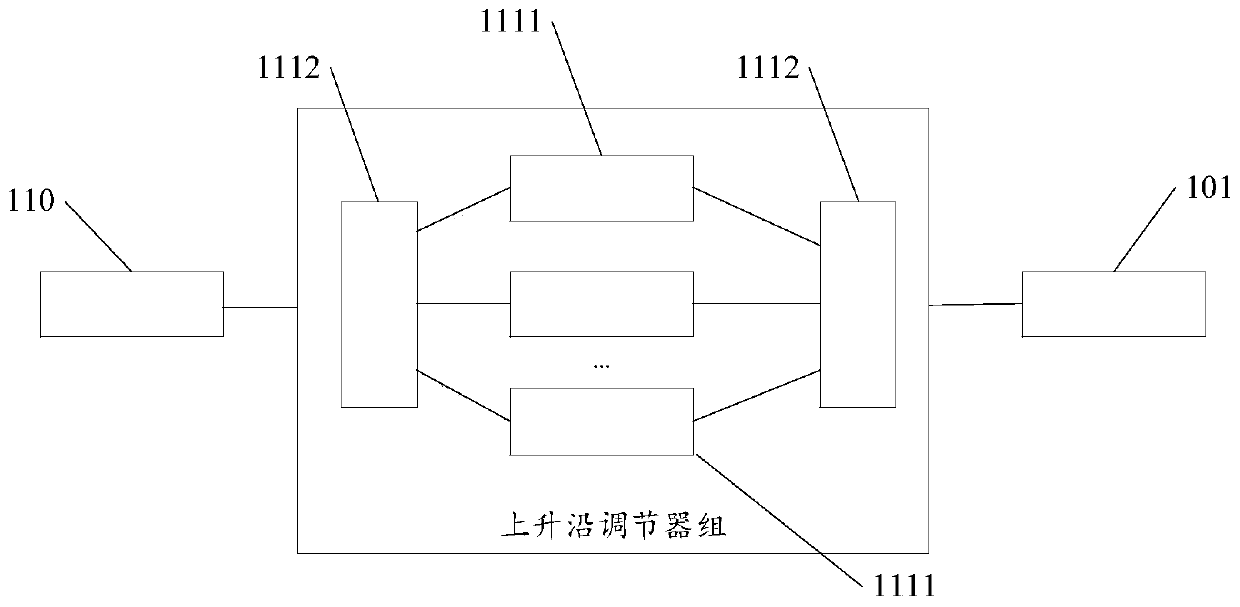
[0035] An embodiment of the present invention provides a transmission line pulse test system, such as figure 1 As shown, including: pulse generating device, pulse testing device;

[0036] Wherein, the output end of the pulse generating device is connected with the pulse testing device, and the pulse generating device inputs the generated pulse signal into the pulse testing device.

[0037] Wherein, the pulse test device includes a...


PUM


Abstract

The invention relates to the technical field of electrostatic discharge protection, and particularly relates to a transmission line pulse test system which comprises a pulse generation device and a pulse test device. An output end of the pulse generation device is connected with the pulse test device; the pulse test device comprises a current detection device, a first transmission line, a coaxialrelay group and a test probe which are connected in sequence, the test probe is used for connecting a first connecting end of a to-be-tested object, the coaxial relay group comprises a first port, andthe first port is connected with the first transmission line; the pulse test device further comprises an oscilloscope, the oscilloscope comprises a first input end and a second input end, the first input end is connected with the current detection device, and the second input end is connected with a second connecting end of the to-be-tested object; and based on a detected forward wave passing through the current detection device and a superimposed wave of the forward wave and a reflected wave at the to-be-tested object, the oscilloscope calculates an accurate current waveform at the to-be-tested object, and provides effective simulation parameters for an electrostatic discharge protection structure.

Description

technical field [0001] The invention relates to the technical field of electrostatic discharge protection, in particular to a transmission line pulse test system. Background technique [0002] The transmission line pulse generator (TLP) is used to measure the IV curve of the device during the process of withstanding electrostatic pulses, and provide the required simulation parameters for the global protection structure of electrostatic discharge (ESD) protection. Most ESD protection will use the transmission line pulse generator. [0003] In the existing TLP system, the probe for detecting current passes through the core wire of the transmission line and is connected in series in the TLP system, so that the probe for detecting current is as close as possible to the object under test, so as to obtain a relatively complete waveform and improve the test accuracy. However, the existing In the TLP system, the technical parameters of the current probe and the stripping of the tran...

Claims


Application Information

Patent Timeline
Patent Type & Authority Applications(China)
IPC IPC(8): G01R19/00G01R29/02
CPCG01R19/0092G01R29/02
Inventor 曾传滨王娟娟倪涛孙佳星罗家俊韩郑生王玉娟张煦
Owner INST OF MICROELECTRONICS CHINESE ACAD OF SCI
Learn More