Fixing device for computer display screen
A technology of fixing device and display screen, which is applied to the structural components, calculation, and supporting machines of portable computers, etc., can solve the problems of inability to adjust the size and discomfort for users, and achieves a simple and reliable fixing method that meets the needs of use. Effect
- Summary
- Abstract
- Description
- Claims
- Application Information
AI Technical Summary
Problems solved by technology
Method used
Image
Examples
Embodiment 1
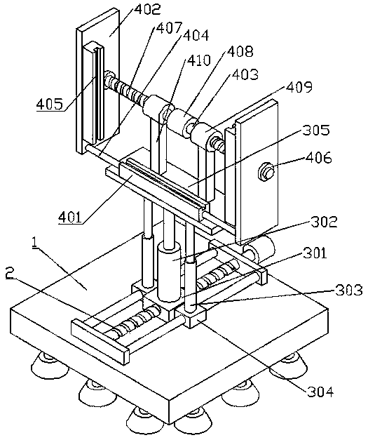
[0026] A fixing device for a computer display screen, comprising a base 1, an adjusting mechanism 2, a lifting mechanism and a fixing mechanism;
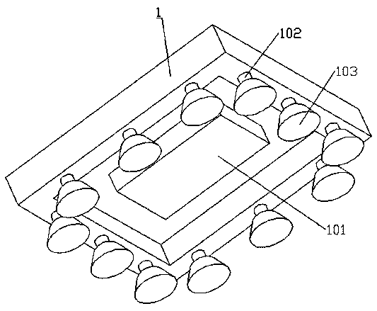
[0027] The base 1 is a cuboid cavity structure with an open bottom. The adjustment mechanism 2 is arranged on the upper surface of the top plate of the base 1. A counterweight 101 is fixedly connected to the center of the lower surface of the top plate of the base 1. The bottom surface of each side plate of the base 1 passes through a support rod 102. A plurality of truncated circular legs 103 are evenly fixed, and the legs 103 are made of hard rubber;
[0028] The lifting mechanism includes an adjustment seat 301, a lifting assembly 302 and a telescopic rod 303. The left and right sides of the adjustment seat 301 are symmetrically fixed with a sliding seat 304. The adjustment seat 301 and the sliding seat 304 are connected with the adjustment mechanism 2. The lifting assembly 302 is fixed on the adjustment On the seat 301, the tele...
Embodiment 2
[0031] The difference from Example 1 is that it also includes the following:
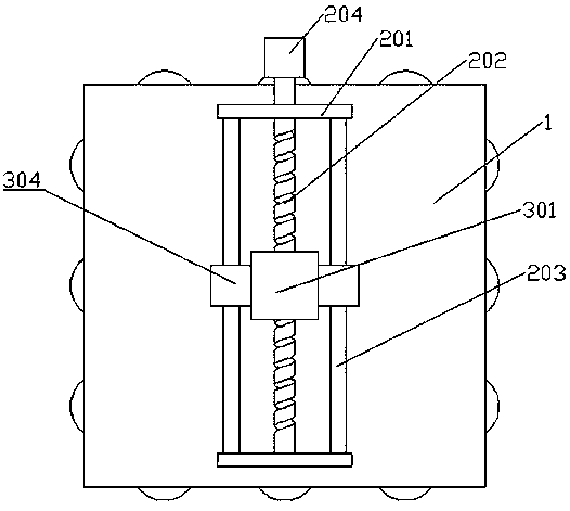
[0032] The adjustment mechanism 2 includes a shaft seat 201, an adjustment screw 202 and a guide rod 203. The shaft seat 201 is symmetrically fixed on the base 1 front and back, the adjustment screw 202 is rotatably connected between the shaft seats 201, and the rear end of the shaft rod 403 extends to the shaft. The seat 201 is fixedly connected with a knob 204, the arc surface of the knob 204 is provided with anti-slip lines, the guide rod 203 is fixedly connected between the shaft seats 201, the guide rod 203 is symmetrically arranged on the left and right sides of the adjusting screw rod 202, and the adjusting seat 301 is engaged with the adjusting screw 202 , and the sliding seat 304 is slidably connected with the guide rod 203 .
Embodiment 3
[0034] The difference from Example 2 is that it also includes the following:
[0035] The lifting assembly 302 includes a sliding sleeve 3021, a lifting screw 3022 and a lifting nut 3023, the bottom of the sliding sleeve 3021 is fixedly connected to the adjustment seat 301, the lifting screw 3022 is slidably connected in the sliding sleeve 3021, and the top of the lifting screw 3022 is fixedly connected to the seat plate 305 , the lifting nut 3023 meshes with the lifting screw 3022, the bottom surface of the lifting nut 3023 is fixedly connected with an annular connecting sleeve 3024, the bottom of the inner wall of the connecting sleeve 3024 is fixedly connected with a limiting ring 3025, and the outer wall of the sliding sleeve 3021 is provided with a sliding ring 3025. The connecting chute 3026.
[0036] working principle
[0037] When in use, the computer display screen is placed in the placement groove of the placement seat 401, and then the shaft 403 is driven to rotate...
PUM
 Abstract
Description
Claims
Application Information
 - Generate Ideas
- Intellectual Property
- Life Sciences
- Materials
- Tech Scout
- Unparalleled Data Quality
- Higher Quality Content
- 60% Fewer Hallucinations
Browse by: Latest US Patents, China's latest patents, Technical Efficacy Thesaurus, Application Domain, Technology Topic, Popular Technical Reports.
© 2025 PatSnap. All rights reserved.Legal|Privacy policy|Modern Slavery Act Transparency Statement|Sitemap|About US| Contact US: help@patsnap.com


