Automatic feeding device of washing machine and using method of automatic feeding device
An automatic feeding and washing machine technology, which is applied to washing devices, other washing machines, applications, etc., can solve the problems of irregular shape of the additive box, easy blockage of the feeding port, easy damage to high-grade fabrics, etc., and achieve regular, square and beautiful appearance, simple and reliable structure , easy to replace the effect
- Summary
- Abstract
- Description
- Claims
- Application Information
AI Technical Summary
Problems solved by technology
Method used
Image
Examples
Embodiment 1
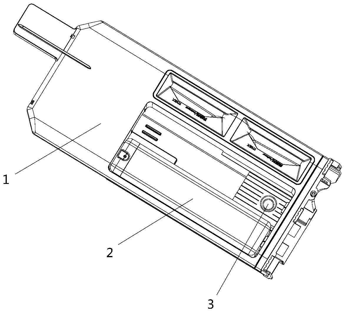
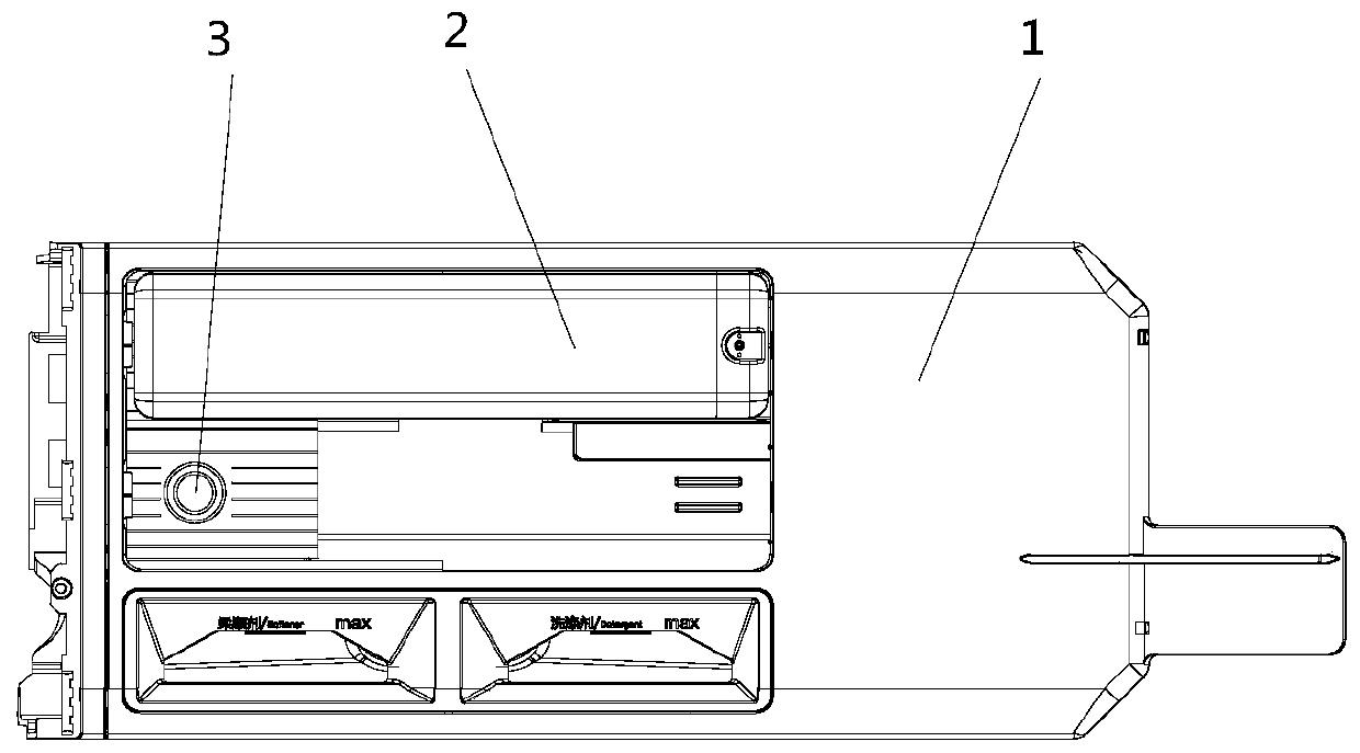
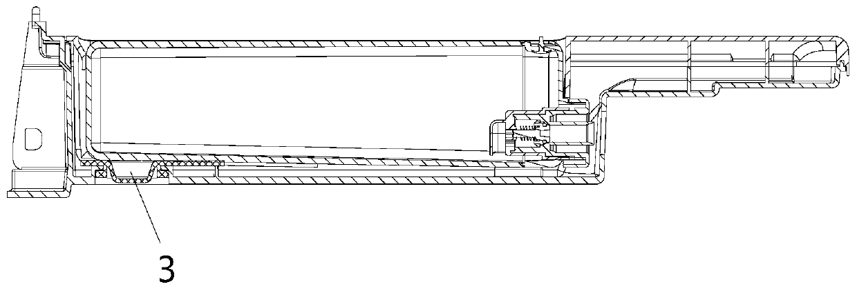
[0075] Such as Figure 1 to Figure 3 As shown, the automatic dispensing device of a washing machine described in this embodiment includes an accommodating chamber 1 that moves between an open position and a closed position; the accommodating chamber 1 is provided with an additive box 2 for storing additives; The bottom of the storage chamber 1 corresponds to the position of the additive box 2, and a force is applied from the outside of the bottom of the storage chamber 1 to push the additive box 2 out of the storage chamber 1. figure 1 It is a schematic diagram of an axonometric view of the automatic dispensing device of the present invention, which mainly shows the automatic dispensing device of the washing machine according to the present invention from the perspective of the axonometric view, from figure 1 It can be seen from the figure that a space for accommodating the additive box 2 is formed in the accommodating chamber 1, and there are at least two positions for instal...
Embodiment 2
[0077] Such as Figure 1 to Figure 3 As shown, this embodiment is a further limitation of the above-mentioned embodiment 1. In the automatic feeding device of a washing machine described in this embodiment, the ejection structure 3 is arranged at a position close to the front end of the accommodating chamber 1, further Specifically, the distance between the ejection structure 3 and the front end of the accommodation chamber 1 is calculated from the shape center of the ejection structure 3 or the edge near the front end of the accommodation chamber 1 .
Embodiment 3
[0079] Such as Figure 1 to Figure 3 As shown, this embodiment is a further limitation of the first or second embodiment above. The distance between the ejection structure 3 and the front end of the accommodating chamber 1 in this embodiment is in a ratio of 1:5 to the length of the additive box 2. ~1:3.
PUM
 Abstract
Description
Claims
Application Information
 - R&D
- Intellectual Property
- Life Sciences
- Materials
- Tech Scout
- Unparalleled Data Quality
- Higher Quality Content
- 60% Fewer Hallucinations
Browse by: Latest US Patents, China's latest patents, Technical Efficacy Thesaurus, Application Domain, Technology Topic, Popular Technical Reports.
© 2025 PatSnap. All rights reserved.Legal|Privacy policy|Modern Slavery Act Transparency Statement|Sitemap|About US| Contact US: help@patsnap.com


