Eureka AIR delivers breakthrough ideas for toughest innovation challenges, trusted by R&D personnel around the world.

Automatic weeding device

An automatic, intermediate-position technology, applied in cutters, agricultural machinery and implements, applications, etc., can solve the problems of on-site mess, unfavorable centralized processing of cutting grass, inconvenient cutting and grass collection operations, etc., to avoid messy, The effect of easy collection and easy upper and lower control

Inactive Publication Date: 2020-07-31
赵菊兰
View PDF9 Cites 4 Cited by
  • Summary
  • Abstract
  • Description
  • Claims
  • Application Information

AI Technical Summary

Problems solved by technology

[0002] Existing weeders are mainly divided into powered weeders and manual weeders. The powered weeder is equipped with an engine on the weeder, and uses the engine to drive the cutting unit to rotate. Therefore, when the user pushes the weeder on the lawn, it can The mowing action is performed automatically. Even if the weeder does not move, the engine and cutting unit can still keep running. Manual weeding does not have a power source such as engine power. It is driven by the wheel or friction wheel when the user pushes the weeder Friction and rolling on the lawn, using the wheel or friction wheel to drive the cutting unit at the bottom of the weeder to rotate at the same time, the existing weeding device is not convenient for the collection of cut grass, resulting in a messy scene, which is not conducive to cutting grass Therefore, it is urgent to develop an automatic weeding device to solve the above problems and facilitate market promotion and application.

Method used


Image

  • Automatic weeding device
  • Automatic weeding device
  • Automatic weeding device

Examples


Embodiment Construction

[0019] The following will clearly and completely describe the technical solutions in the embodiments of the present invention with reference to the accompanying drawings in the embodiments of the present invention. Obviously, the described embodiments are only some, not all, embodiments of the present invention. Based on the embodiments of the present invention, all other embodiments obtained by persons of ordinary skill in the art without making creative efforts belong to the protection scope of the present invention.

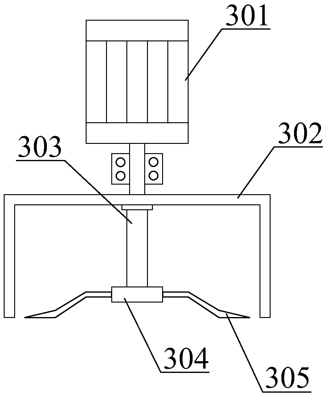
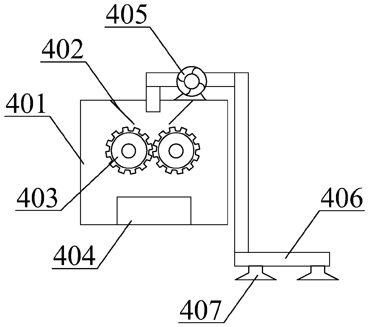
[0020] see Figure 1-4 , the present invention provides a technical solution: an automatic weeding device, such as figure 1 As shown, it includes base plate 1, walking wheel 2, weeding assembly 3, collecting assembly 4, soil loosening assembly 5, gasoline engine 6, push handle 7, first button switch 8 and second button switch 9, and described walking wheel 2 adopts four One, and the walking wheel 2 is fixed below the base plate 1 by bolts; the push handle 7 i...


PUM


Abstract

The invention discloses an automatic weeding device. The automatic weeding device comprises a bottom plate, travelling wheels, a weeding assembly, a collecting assembly, a soil loosening assembly, a gasoline engine, a push handle, a first button switch and a second button switch; due to arrangement of the collecting assembly, when weeding is carried out, an exhaust fan is electrified to run; cut grass is collected through a collecting cover, and conveyed into a collecting box through a collecting pipe; crushing rollers perform crushing on the cut grass; collecting of the cut grass is conveniently carried out; centralized processing of the cut grass is easily carried out; a guide plate performs diversion on the cut grass; the fact that the cut grass smoothly enters to be between the crushing rollers can be ensured; due to arrangement of the soil loosening assembly, when soil loosening operation needs to be carried out, the second button switch is pressed; an electric push rod pushes a support plate to move downwardly; therefore, a soil loosening cutter is contacted with the ground; a soil loosening motor drives a soil loosening disc and the soil loosening cutter to rotate; therefore, soil loosening operation on the ground is carried out; the functionality of the weeding device is improved; vertical control of the soil loosening cutter is conveniently carried out through the electric push rod; and thus, the practicability of the soil loosening assembly is improved.

Description

technical field [0001] The invention relates to the technical field of weeding equipment, in particular to an automatic weeding device. Background technique [0002] Existing weeders are mainly divided into powered weeders and manual weeders. The powered weeder is equipped with an engine on the weeder, and uses the engine to drive the cutting unit to rotate. Therefore, when the user pushes the weeder on the lawn, it can The mowing action is performed automatically. Even if the weeder does not move, the engine and cutting unit can still keep running. Manual weeding does not have a power source such as engine power. It is driven by the wheel or friction wheel when the user pushes the weeder Friction and rolling on the lawn, using the wheel or friction wheel to drive the cutting unit at the bottom of the weeder to rotate at the same time, the existing weeding device is not convenient for the collection of cut grass, resulting in a messy scene, which is not conducive to cutting ...

Claims


Application Information

Patent Timeline
Patent Type & Authority Applications(China)
IPC IPC(8): A01D43/12A01D43/077A01D43/08
CPCA01D43/086A01D43/12
Inventor 赵菊兰
Owner 赵菊兰
Why Eureka
Eureka Blog
Learn More