Sealing structure and liquid storage container

A technology for a liquid accommodating container and a sealing structure, which is applied in the directions of printing and printing devices, etc., can solve the problems of the deterioration of the sealing performance of the flow path and the deformation of the sealing parts in the sealing structure.

Active Publication Date: 2020-07-28
SEIKO EPSON CORP
View PDF9 Cites 0 Cited by
  • Summary
  • Abstract
  • Description
  • Claims
  • Application Information

AI Technical Summary

Problems solved by technology

[0006] However, since the opening surface of the liquid outlet part to which the film is heat-sealed is close to the sealing member, welding burrs generated by thermal welding of the film and the liquid outlet part may come into contact with the sealing member.
In this case, the sealing part may be deformed by the pressure exerted by the welding burr
When the sealing member is deformed, there is a problem that the airtightness of the flow path in the sealing structure deteriorates

Method used


Image

  • Sealing structure and liquid storage container
  • Sealing structure and liquid storage container
  • Sealing structure and liquid storage container

Examples


Deformed example 2

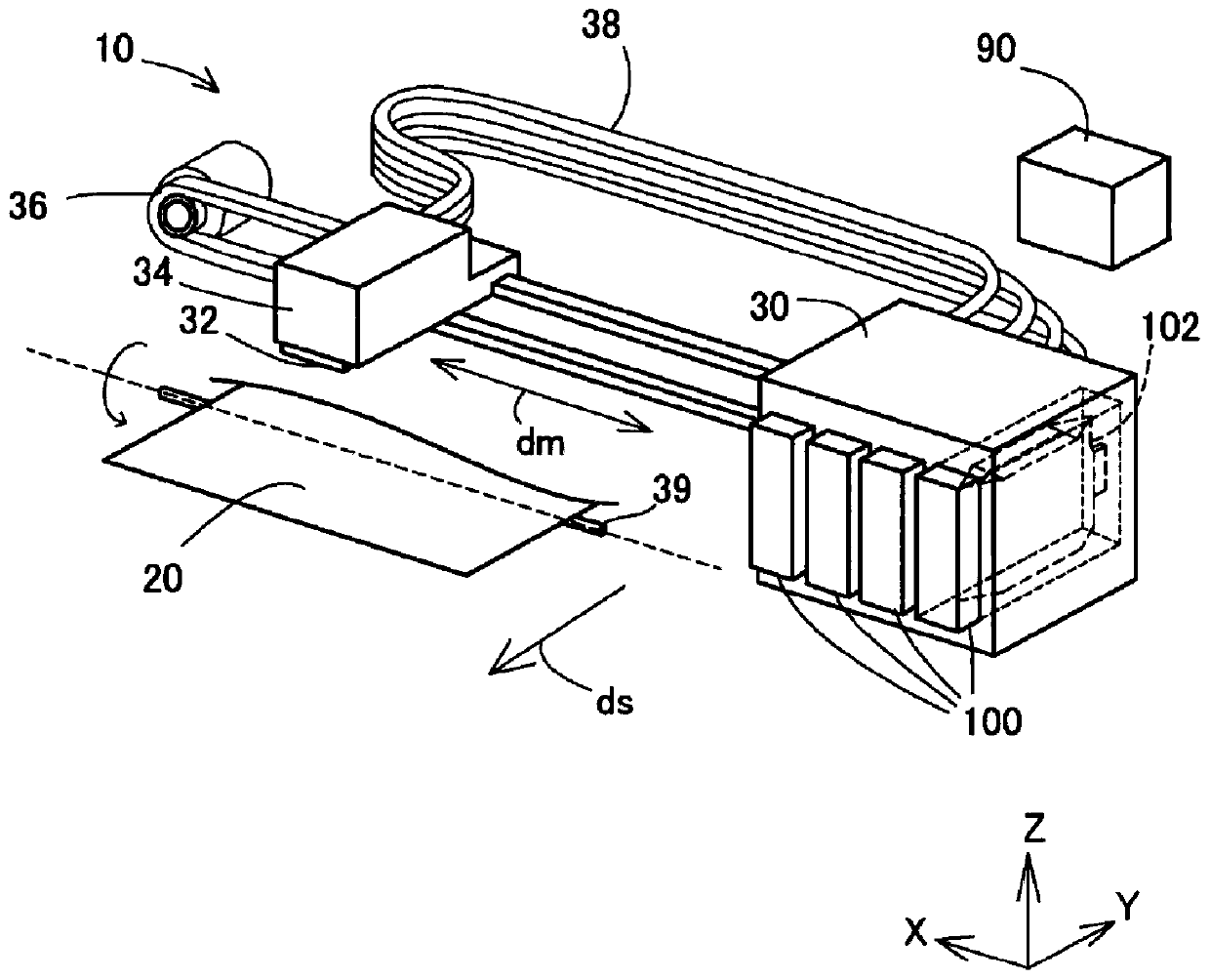
[0053] Although the liquid storage container 100 of the above-mentioned embodiment has been described as an inkjet printer and a container for supplying ink to the inkjet printer, it is not limited thereto, and can also be applied to ejection of various liquids containing ink. Any liquid ejection device, and a liquid tank for containing its liquid.

[0054] The content derived from the embodiment is described below.

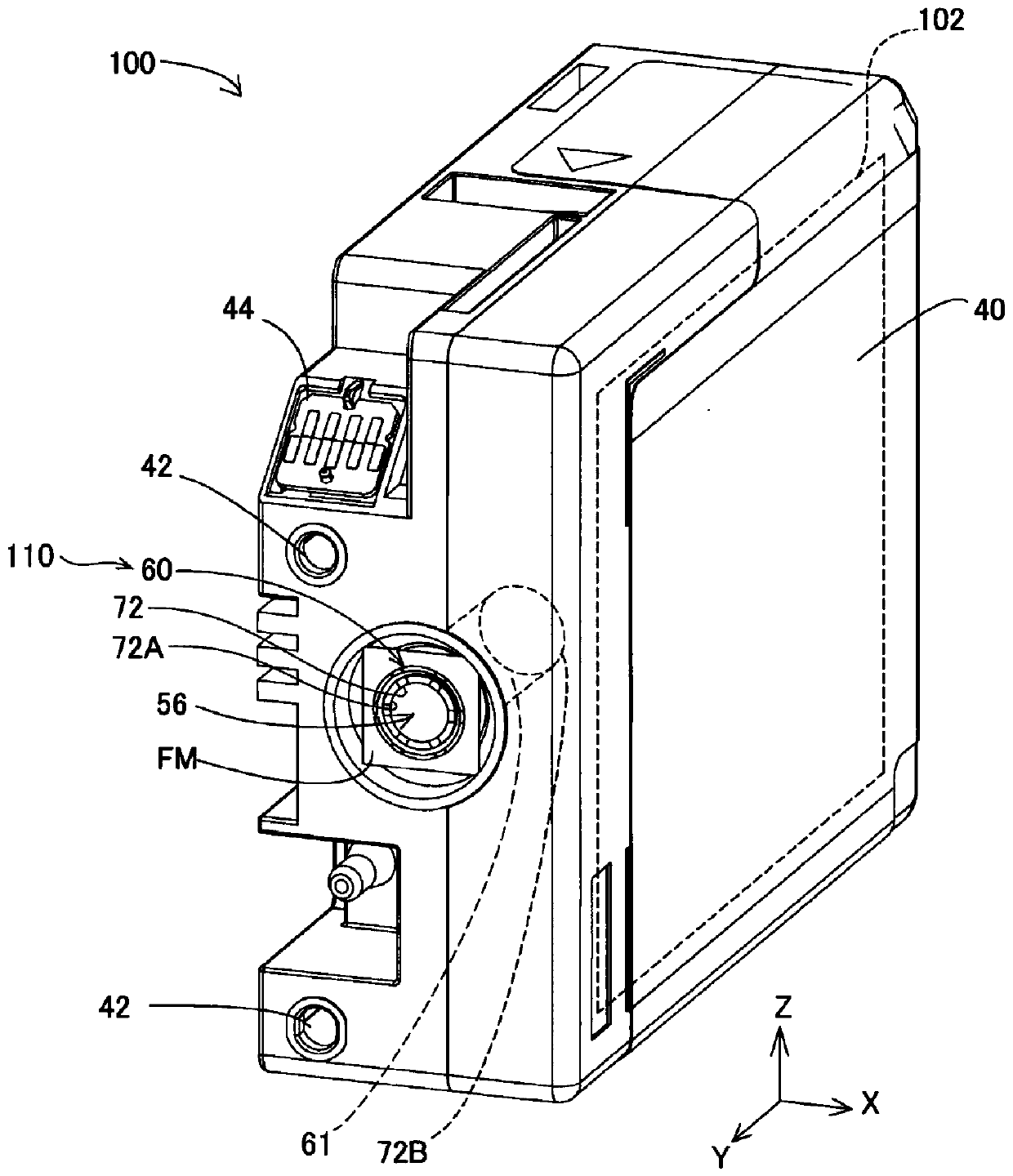
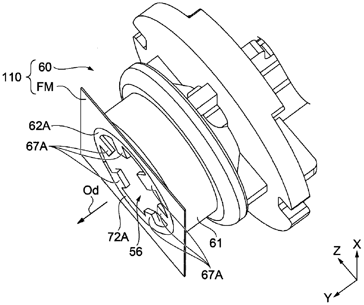
[0055]A sealed structure, which is a sealed structure of a liquid storage container, is characterized in that it includes: a liquid outlet part formed with an opening for leading out the liquid in the liquid storage container; The opening portion, the liquid outlet portion has: a flow path forming member, which forms a flow path leading to the opening portion; and a sealing member, which is arranged in the flow path, in the flow path forming member A welding protrusion protruding further from a surface of the sealing member on the side of the opening is formed, ...


PUM


Abstract

The invention provides a sealing structure of a liquid container, which can prevent deformation of a sealing part caused by welding burrs. The sealing structure includes a liquid supplying section having an opening for supplying a liquid in the liquid storage container, and a film member covering the opening. The liquid supplying section includes a flow path forming member having a flow path communicating with the opening, and a sealing member disposed in the flow path, and the flow path forming member has a welding protrusion protruding from a surface of the sealing member on the opening side, the film member is welded to the welding protrusion, and the film member and the sealing member are spaced from each other.

Description

technical field [0001] The present invention relates to a sealed structure and a liquid container. Background technique [0002] Conventionally, as described in Patent Document 1, a sealing structure in which a film is thermally welded to an opening surface of a liquid outlet portion forming a liquid passage is known. In this sealed structure, a sealing member is provided in the liquid passage of the liquid outlet portion. [0003] [Prior art literature] [0004] [Patent Document] [0005] [Patent Document 1]: Japanese Patent Laid-Open No. 2008-230214 [0006] However, since the opening surface of the liquid outlet portion to which the film is thermally welded is close to the sealing member, welding burrs generated by thermal welding of the film and the liquid outlet portion may come into contact with the sealing member. In this case, the sealing part may be deformed by the pressure exerted by the welding burr. When the sealing member is deformed, there is a problem tha...

Claims


Application Information

Patent Timeline
Patent Type & Authority Applications(China)
IPC IPC(8): B41J2/175
CPCB41J2/17553B41J2/17513B41J2/17523B41J2/17509B41J29/13B41J2/1753
Inventor 内藤直树
Owner SEIKO EPSON CORP
Why Eureka
Try Eureka