Disk lifting and grasping device

A grasping device and hanging plate technology, applied in the directions of manipulators, chucks, manufacturing tools, etc., can solve the problems of unstable grasping, troublesome debugging, and large space occupation, so as to reduce the cost of accessories, meet production needs, and improve work efficiency. The effect of efficiency

Pending Publication Date: 2020-07-28
WUXI JUYI TONGCHUANG TECH CO LTD
View PDF0 Cites 1 Cited by
  • Summary
  • Abstract
  • Description
  • Claims
  • Application Information

AI Technical Summary

Problems solved by technology

[0003] At present, some of the transfers of full or empty trays are done manually, which is not conducive to the realization of automatic production, and some of them are equipped with a manipulator on the conveyor line to grab the reel.
However, the existing manipulator has a complex structure and takes up a relatively large space; and it is unstable when grasping from the outside of the wire reel, which cannot meet the high-speed production requirements; Replacement of equipment components, troublesome debugging, high cost

Method used


Image

  • Disk lifting and grasping device
  • Disk lifting and grasping device
  • Disk lifting and grasping device

Examples


Embodiment 1

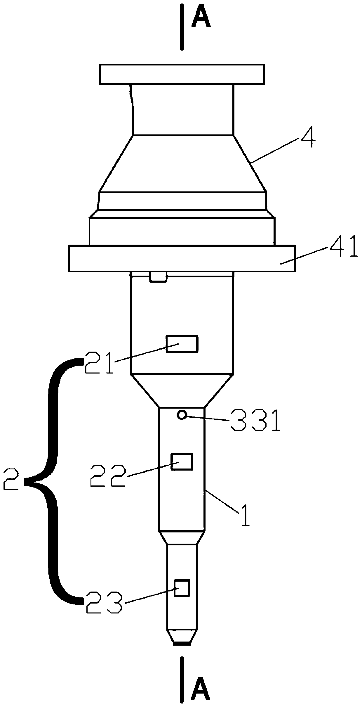
[0022] Such as figure 1 and 2 As shown, the hanging pan grabbing device according to one embodiment of the present invention includes a hanging pan shaft 1, the hanging pan shaft 1 is a hollow structure, the hanging pan shaft 1 is connected with a hinge block assembly 2, and the hinge block assembly 2 can extend or Retract on the outer wall of the suspension shaft 1. When the pan needs to be hoisted, the pan shaft 1 is inserted into the center hole of the pan from above, and the hinge block assembly 2 protrudes from the outer wall of the pan shaft 1, and hooks the lower surface of the top surface of the pan from the center hole of the pan , the structure of the lifting pan grabbing device is compact, the pan is hoisted from the inside, and the occupied space is small, and in the process of transfer, the hoisting of the pan from the inside is more stable than the grabbing of the pan from the outside.

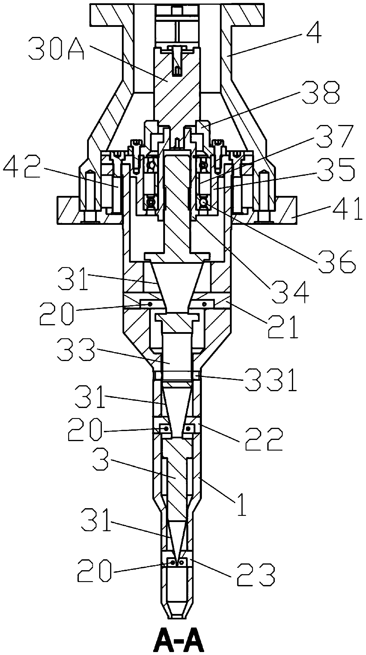
[0023] Such as image 3 As shown, in order to control the telescopic or r...

Embodiment 2

[0029] Such as Figure 5 As shown, the main difference between Embodiment 2 and Embodiment 1 is that the control shaft driving member 30 that drives the control shaft 3 is different. In this embodiment, pneumatic control is mainly used.

[0030] Such as Figures 5 to 7 As shown, the control shaft driving part 30 is a cylinder 30B, the top of the suspension plate shaft 1 is installed with an end cover assembly 1 51 through bolts, and the end cover assembly 1 51 is installed with an end cover assembly 2 52 through bolts, and the cylinder body of the cylinder 30B is fixedly installed In the end cover assembly 2 52 , the piston rod of the cylinder 30B passes through the end cover assembly 1 51 and connects to the top of the control shaft 3 . The cylinder body of the air cylinder 30B is housed in the fixed sleeve 4 , the lower cover plate 41 is installed by bolts at the lower end of the fixed sleeve 4 , and a guide post 42 is arranged between the lower cover plate 41 and the susp...


PUM


Abstract

The invention discloses a disk lifting and grasping device. The device comprises a disk lifting shaft; the disk lifting shaft adopts the hollow structure; the disk lifting shaft is connected with hinge block components; the hinge block components can extend out of or retract back to the outer wall of the disk lifting shaft; and a control shaft capable of moving up and down is arranged in the disklifting shaft. When the device is used for grasping a disk, the disk lifting shaft is inserted in a central hole of the disk, the control shaft capable of moving up and down drives the hinge block components to extend out or retract back, when the hinge block components extends out of the outer wall of the disk lifting shaft, the hinge block components hook the lower surface of the top surface ofthe disk from the inside of the central hole of the disk, the disk is lifted from the inside, the equipment occupies small space, in the lifting and moving process of the disk, the stability of the disk when the disk is lifted from the inside is higher than that of the disk when grasped from the outer side, and multiple groups of the hinge block components are arranged so as to improve the universality of the device.

Description

technical field [0001] The invention relates to enameled wire manufacturing equipment, and more particularly to a hanging pan grabbing device. Background technique [0002] The enameled wire is composed of the inner wire and the coating that wraps the wire. During the production process of the enameled wire, the wire needs to be wound on the wire reel by a wire take-up device. After the wire reel is wound, it is necessary to transfer the full reel in time to replace it with an empty reel in time. [0003] At present, some of the transfers of full or empty trays are operated purely manually, which is not conducive to the realization of automatic production. In some cases, a manipulator is set on the conveying line to grab the wire tray. However, the existing manipulator has a complex structure and takes up a relatively large space; and it is unstable when grasping from the outside of the wire reel, which cannot meet the high-speed production requirements; It is troublesome ...

Claims


Application Information

Patent Timeline
Patent Type & Authority Applications(China)
IPC IPC(8): B25J15/00
CPCB25J15/0023
Inventor 张伟新蔡麟梁骁军郎宁卡
Owner WUXI JUYI TONGCHUANG TECH CO LTD
Why Eureka
Try Eureka