
Satellite-borne tripe-frequency beacon and working method thereof

A tri-frequency beacon, satellite-borne technology, applied in satellite radio beacon positioning systems, measuring devices, instruments, etc., can solve the problems of loss of tri-frequency beacon function, occultation receiver interference, etc., to overcome electromagnetic compatibility problem, the effect of solving the in-band interference problem

Pending Publication Date: 2020-07-24
中国电波传播研究所
View PDF6 Cites 2 Cited by
  • Summary
  • Abstract
  • Description
  • Claims
  • Application Information

AI Technical Summary

Problems solved by technology

[0003] At present, most of the space-borne beacons in the world are dual-frequency beacons, and there are no domestic products of space-borne triple-frequency beacons. Foreign space-borne triple-frequency beacons have only been reported on COSMIC satellites. Since the satellite is also equipped with a GNSS occultation receiver, and the L-band signal of the tri-frequency beacon machine and the signal formed by intermodulation with the VHF and UHF bands will interfere with the occultation receiver, the COSMIC satellite was launched in orbit. Afterwards, the L-band signal of the tri-frequency beacon machine has been turned off, and only two beacon signals of the VHF band and the UHF band are transmitted, losing the function of the tri-band beacon

Method used


Image

  • Satellite-borne tripe-frequency beacon and working method thereof
  • Satellite-borne tripe-frequency beacon and working method thereof
  • Satellite-borne tripe-frequency beacon and working method thereof

Examples


Embodiment 1

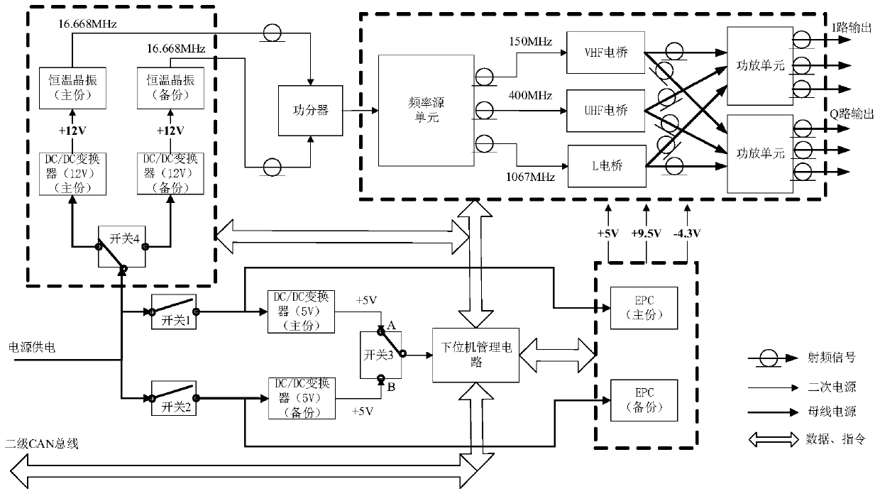
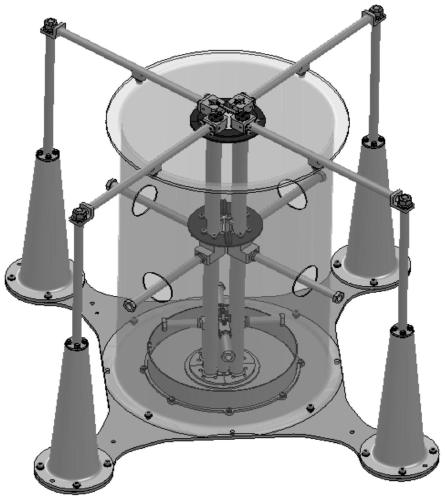
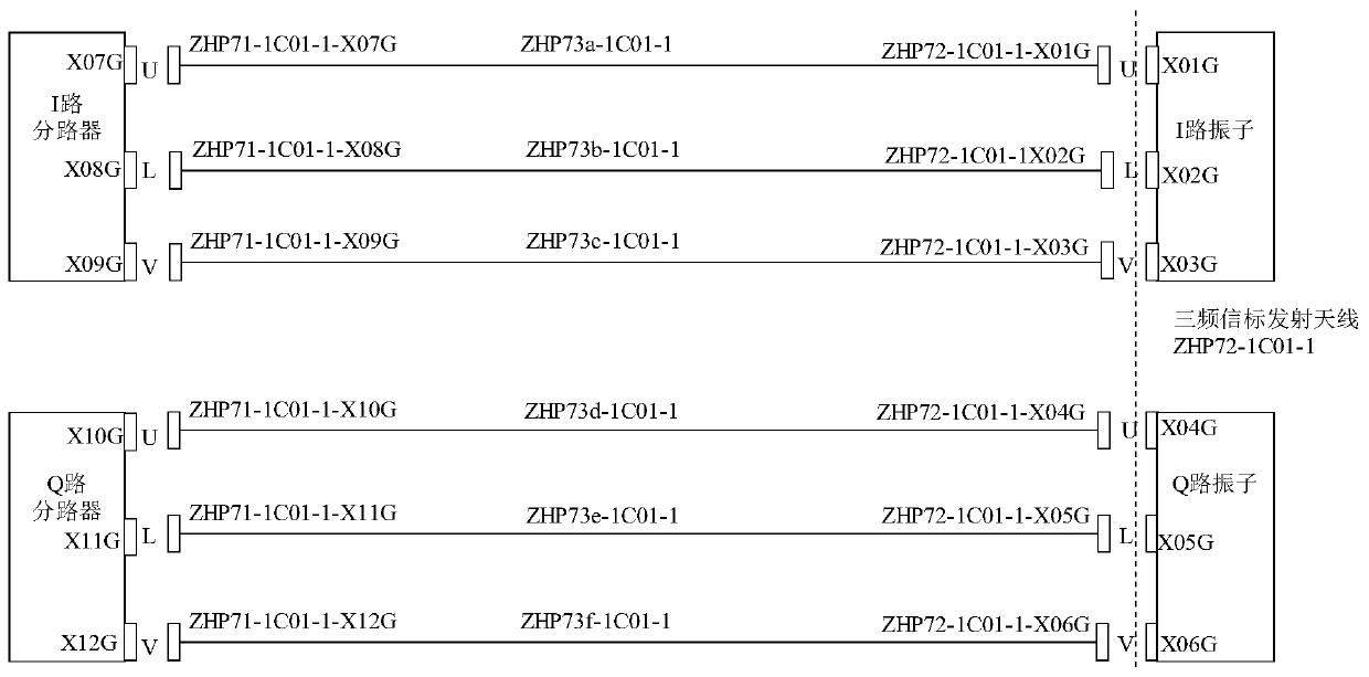
[0024] Embodiment 1, the space-borne triple-frequency beacon machine of this embodiment transmits coherent signals of VHF (150.012MHz), UHF (400.032MHz) and L (1066.752MHz) three frequency bands from the satellite, and realizes the ionosphere by receiving on the ground The large-scale, high-time resolution, and high-level resolution three-dimensional scanning requires that the ionospheric peak electron density retrieval accuracy error of the triple-frequency beacon detection system be less than 10%. The space-borne tri-frequency beacon machine is the space-borne part of the tri-frequency beacon detection system, which is mainly composed of a transmitter, a transmitting antenna and a radio frequency connection cable between them.

[0025] The transmitter of the spaceborne tri-frequency beacon machine has the function of transmitting VHF / UHF / L three frequency beacon signals to the ground tri-frequency beacon receiver station. The transmitter generates three frequency-coherent be...


PUM


Abstract

The invention relates to a satellite-borne tripe-frequency beacon and a working method thereof. The satellite-borne tripe-frequency beacon comprises an emitter, an emission antenna and a radio-frequency connection cable, wherein the radio-frequency connection cable is arranged between the emitter and the emission antenna, the emitter comprises a constant temperature crystal oscillator and a frequency source unit, the frequency source unit is electrically connected with the constant temperature crystal oscillator, coherent signals, generated by the frequency source unit, at VHF, UHF and L bandsare orthogonalized by a bridge and then synthesized and amplified by a power amplifier to output an I / Q signal, a lower computer management circuit for controlling each part in the emitter to work communicates with a satellite service through a CAN bus, and a power unit supplies power to each part in the emitter. With the satellite-borne tripe-frequency beacon disclosed by the invention, three coherent signals at the VHF, UHF and L bands can be initially and simultaneously emitted, the problem of electromagnetic compatibility of the tripe-frequency beacon and a GNSS occultation receiver is solved, the problem of in-band interference of the GNSS occultation receiver is effectively solved, normal working of the beacon is ensured, and meanwhile, normal working of the GNSS occultation receiver is not affected.

Description

technical field [0001] The invention belongs to the research field of space-borne ionospheric environment monitoring, and particularly relates to a space-borne three-frequency beacon machine for ionospheric electron density monitoring and its working method in the field. Background technique [0002] The space-borne triple-frequency beacon machine is mounted on the satellite platform, which can scan the ionosphere in a large range, with high time resolution and high horizontal resolution, and can scan the state of the ionosphere above the F2 layer and the small-scale ionosphere It is a new space-based ionospheric detection technology that can obtain high-precision ionospheric TEC and ionospheric electron density and other information by measuring the inhomogeneous body structure. [0003] At present, most of the space-borne beacons in the world are dual-frequency beacons, and there are no domestic products for space-borne triple-frequency beacons. Foreign space-borne triple-...

Claims


Application Information

Patent Timeline
IPC IPC(8): G01R29/08G01S19/03
CPCG01R29/08G01S19/03
Inventor 孙芳袁亚平甄卫民刘森杨光张宇环
Owner 中国电波传播研究所
Learn More