Shock-resistant type sand mould bearing device

A technology of bearing device and molding sand, applied in molding table, spring/shock absorber, vibration suppression adjustment, etc., can solve the problems of affecting the quality of the model, affecting the quality of castings, easy to shake, etc.

Inactive Publication Date: 2020-07-24
WUHU JINMAO FLUID TECH CO LTD
View PDF4 Cites 0 Cited by
  • Summary
  • Abstract
  • Description
  • Claims
  • Application Information

AI Technical Summary

Problems solved by technology

[0002] Sand casting is a widely used form of casting; as the name suggests, sand is used to create molds, sand casting involves placing a finished part model or wooden model in the sand, then filling the pattern with sand at the weekend and removing the pattern from the box In the future, the sand forms the mold. In order to take out the mold before casting the metal, the mold should be made into two or more parts. During the mold making process, holes and vent holes for pouring metal into the mold must be left to form a pouring system. After the metal liquid is poured into the mold, it is kept for an appropriate time until the metal is solidified. After the parts are taken out, the mold is destroyed, so a new mold must be made for each casting; It is easy to shake, which affects the quality of the model, which in turn affects the quality of the casting

Method used


Image

  • Shock-resistant type sand mould bearing device
  • Shock-resistant type sand mould bearing device

Examples


Embodiment Construction

[0016] In order to make the technical means, creative features, goals and effects achieved by the present invention easy to understand, the present invention will be further elaborated below in conjunction with specific embodiments:

[0017] Therefore, the following detailed description of the embodiments of the present invention provided in the accompanying drawings is not intended to limit the scope of the claimed invention, but only represents selected embodiments of the present invention, based on the embodiments of the present invention, All other embodiments obtained by persons of ordinary skill in the art without creative efforts fall within the protection scope of the present invention.

[0018] It should be noted that like numerals and letters denote similar items in the following figures, therefore, once an item is defined in one figure, it does not require further definition and explanation in subsequent figures.

[0019] The terms "first", "second", "third", etc. a...


PUM


Abstract

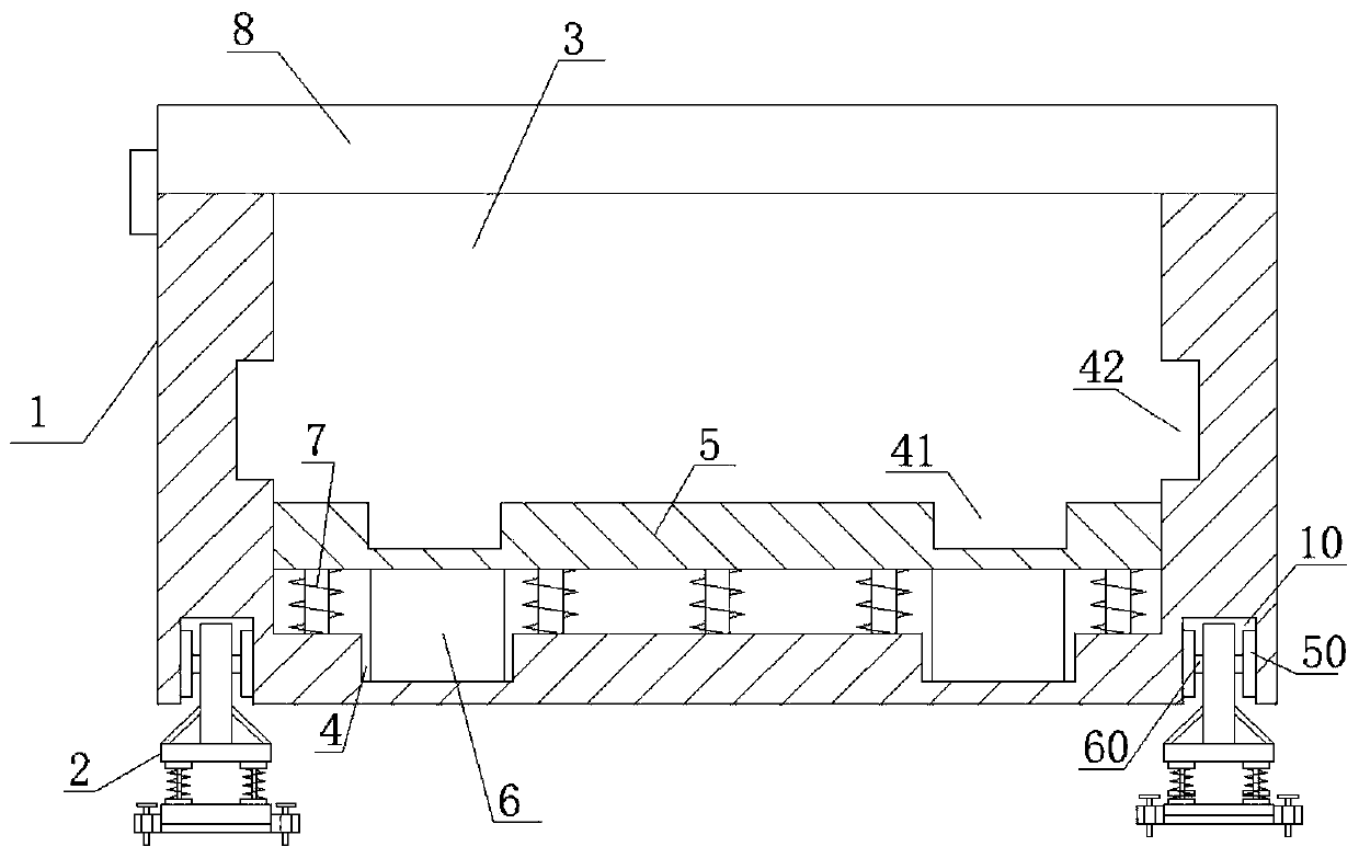
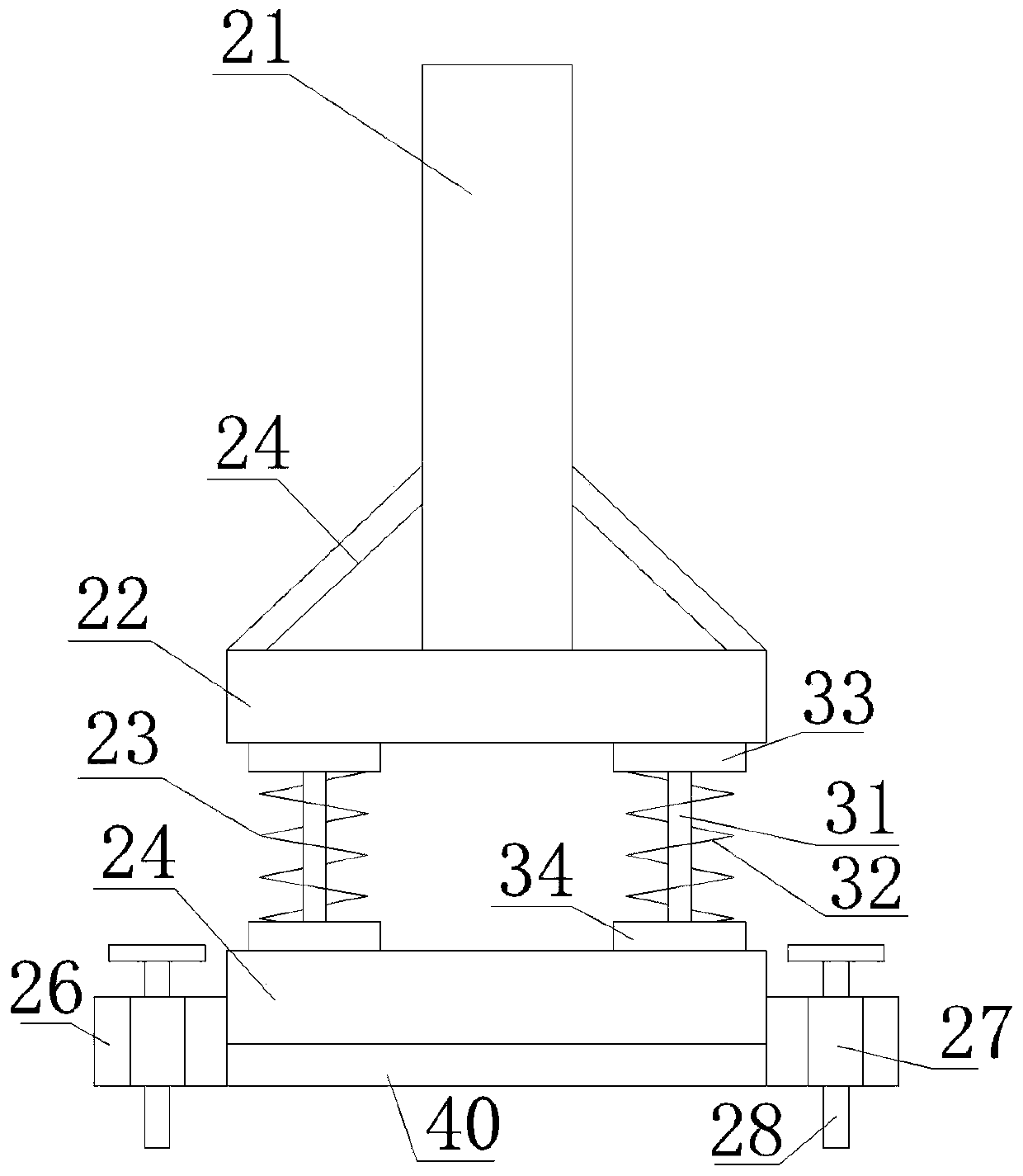
The invention discloses a shock-resistant type sand mould bearing device. The bearing device comprises a bearing device body and shock absorption devices; a placing tank is formed in the bottom of theinner surface of the bearing device; a limiting groove is formed in the surface of the placing tank and is symmetrical relative to the central line of the surface; a load bearing plate is further arranged in the bearing device body; limiting blocks are arranged below the load bearing plate and correspond to the limiting groove; the load bearing plate is fixedly connected with the bottom of the inner surface of the bearing device body via buffer springs; a fixing groove is formed in each of two sides of the lower end surface of the bearing device body; the shock absorption devices are arrangedin the fixing grooves; each shock absorption device comprises a connecting pole, an upper fixed plate, a shock absorber and a lower fixed plate; the upper fixed plate is arranged above the lower fixed plate; the shock absorber is arranged between the upper fixed plate and the lower fixed plate; and the connecting pole is fixedly installed on the upper end face of the upper fixed plate and is connected with the fixing groove. Via the arrangement of the shock absorption devices on the bearing device body and buffer assemblies arranged therein, collision- or shock-caused swaying of a sand mouldin the process of model manufacturing is effectively lessen.

Description

technical field [0001] The invention belongs to the technical field of sand mold equipment, and in particular relates to an anti-shock sand mold bearing device. Background technique [0002] Sand casting is a widely used form of casting; as the name suggests, sand is used to create molds, sand casting involves placing a finished part model or wooden model in the sand, then filling the pattern with sand at the weekend and removing the pattern from the box In the future, the sand forms the mold. In order to take out the mold before casting the metal, the mold should be made into two or more parts. During the mold making process, holes and vent holes for pouring metal into the mold must be left to form a pouring system. After the metal liquid is poured into the mold, it is kept for an appropriate time until the metal is solidified. After the parts are taken out, the mold is destroyed, so a new mold must be made for each casting; It is easy to shake, which affects the quality o...

Claims


Application Information

Patent Timeline
IPC IPC(8): B22C19/02F16F15/067
CPCB22C19/02F16F15/067
Inventor 孙述全孙雄
Owner WUHU JINMAO FLUID TECH CO LTD
Why Eureka
Try Eureka