
User side energy storage system capacity optimization power supply method and device

An energy storage system, capacity optimization technology, applied to circuit devices, AC networks with energy trade/energy transmission authority, electrical components, etc., can solve the problem of reducing the power supply of the energy storage system, not fully considering the aging law of the energy storage system, Issues such as energy storage system capacity allocation and immature power supply strategy

Pending Publication Date: 2020-07-17
深圳龙电埃瑞斯新能源有限公司
View PDF2 Cites 0 Cited by
  • Summary
  • Abstract
  • Description
  • Claims
  • Application Information

AI Technical Summary

Problems solved by technology

[0003] At present, the energy storage system capacity configuration and power supply strategy for the above-mentioned applications are not mature. First, the traditional method of equal reduction is simply based on the value of the maximum electric energy demand higher than the target maximum demand for the time period exceeding the target maximum demand. The target maximum demand can be achieved, but the power supply of the energy storage system cannot be minimized, resulting in a greater demand for the capacity of the energy storage system and an increase in cost; secondly, the energy storage is only determined by comparing the economic benefits of a few target maximum demand System capacity and power supply strategy, and the aging law of the energy storage system is not fully considered in the process, resulting in the inability to optimize the capacity configuration of the energy storage system, and there is a large deviation in the calculation of global revenue

Method used


Image

  • User side energy storage system capacity optimization power supply method and device
  • User side energy storage system capacity optimization power supply method and device
  • User side energy storage system capacity optimization power supply method and device

Examples


Embodiment Construction

[0094] The following will clearly and completely describe the technical solutions in the embodiments of the present invention with reference to the accompanying drawings in the embodiments of the present invention. Obviously, the described embodiments are some of the embodiments of the present invention, but not all of them. Based on the embodiments of the present invention, all other embodiments obtained by persons of ordinary skill in the art without making creative efforts belong to the protection scope of the present invention.

[0095] It should be understood that when used in this specification and the appended claims, the terms "comprising" and "comprises" indicate the presence of described features, integers, steps, operations, elements and / or components, but do not exclude one or Presence or addition of multiple other features, integers, steps, operations, elements, components and / or collections thereof.

[0096] It should also be understood that the terminology used ...


PUM


Abstract

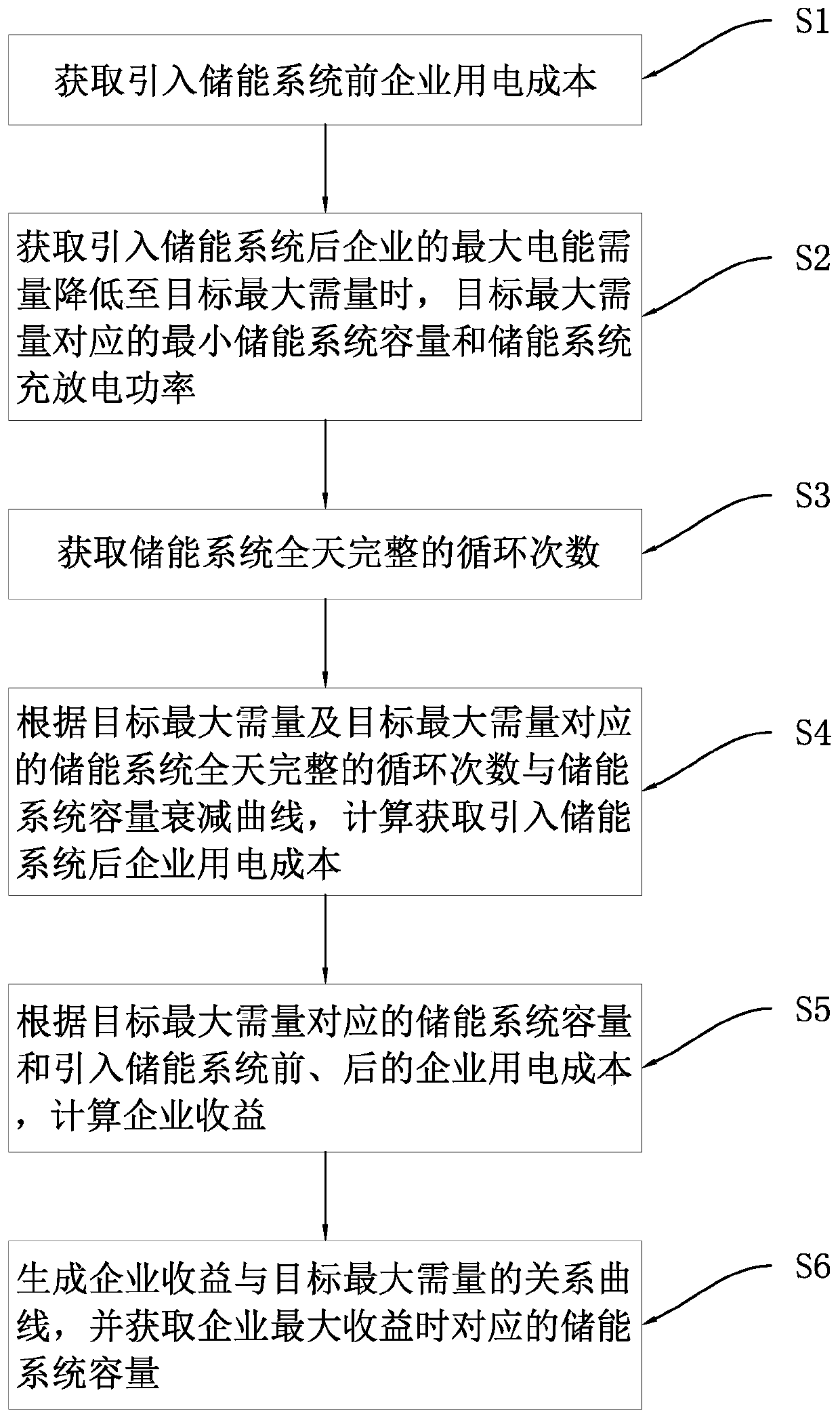
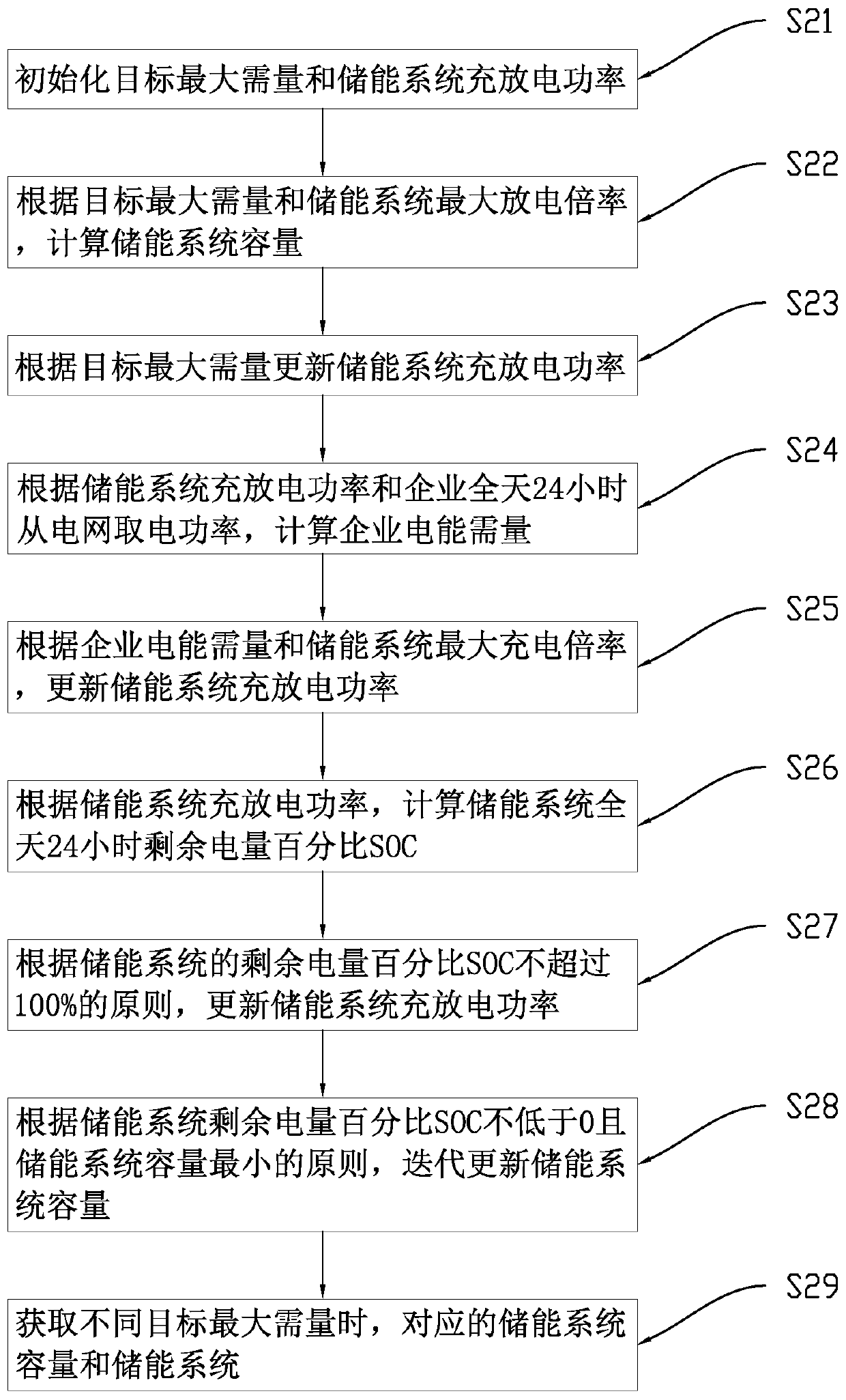
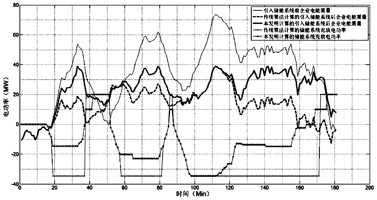
The invention relates to a user side energy storage system capacity optimization power supply method and device. The method comprises the following steps: obtaining the enterprise power consumption cost before the introduction of an energy storage system; obtaining the minimum energy storage system capacity and the energy storage system charging and discharging power corresponding to the target maximum demand when the maximum electric energy demand of the enterprise is reduced to the target maximum demand after the energy storage system is introduced; obtaining the complete cycle index of theenergy storage system all day long; calculating and obtaining the enterprise power consumption cost after the energy storage system is introduced; calculating enterprise income; and generating a relation curve of the enterprise revenue and the target maximum demand, and obtaining the corresponding energy storage system capacity when the enterprise revenue is maximum. By distributing the output power of the energy storage system as required and making full use of the intermittent period for charging, the capacity minimization of the energy storage system can be ensured while the maximum electric energy demand of an enterprise is reduced to the target maximum demand, the cost is reduced, and the accuracy is high.

Description

technical field [0001] The present invention relates to the technical field of capacity-optimized power supply of a user-side energy storage system, and more specifically refers to a method and device for capacity-optimized power supply of a user-side energy storage system. Background technique [0002] Enterprises with large electricity consumption usually build their own thermal power plants. On the one hand, they can return excess electricity to the grid for profit during the low power consumption period at night. amount, thereby reducing electricity costs. However, the price of selling excess production is usually low, and the economic benefits are not good. With the rise of the energy storage industry, the above problems have been improved, that is, through the user-side energy storage system to store a part of the excess power generation, the thermal power station and the energy storage system will supply power to the enterprise during the peak power consumption durin...

Claims


Application Information

Patent Timeline
IPC IPC(8): H02J3/28H02J3/00
CPCH02J3/28H02J3/008Y02P80/10
Inventor 熊磊王立汪林军严哲清谢腾
Owner 深圳龙电埃瑞斯新能源有限公司
Learn More