
Automatic welding device

An automatic welding and welding torch technology, which is applied in auxiliary devices, welding equipment, auxiliary welding equipment, etc., can solve the problems of unsuitable large parts and low welding efficiency, and achieve the effect of improving welding efficiency and reducing handling work

Active Publication Date: 2020-07-10
深圳市德洋实验设备有限公司
View PDF5 Cites 4 Cited by
  • Summary
  • Abstract
  • Description
  • Claims
  • Application Information

AI Technical Summary

Problems solved by technology

Solve the technical problems that the existing welding device has low welding efficiency and is not suitable for large parts

Method used


Image

  • Automatic welding device
  • Automatic welding device
  • Automatic welding device

Examples


Embodiment Construction

[0045] The following will clearly and completely describe the technical solutions in the embodiments of the present invention with reference to the accompanying drawings in the embodiments of the present invention. Obviously, the described embodiments are only some, not all, embodiments of the present invention. Based on the embodiments of the present invention, all other embodiments obtained by persons of ordinary skill in the art without creative efforts fall within the protection scope of the present invention.

[0046] In describing the present invention, it is to be understood that the terms "opening", "upper", "lower", "thickness", "top", "middle", "length", "inner", "surrounding" etc. Indicating orientation or positional relationship is only for the convenience of describing the present invention and simplifying the description, and does not indicate or imply that the components or elements referred to must have a specific orientation, be constructed and operated in a sp...


PUM


Abstract

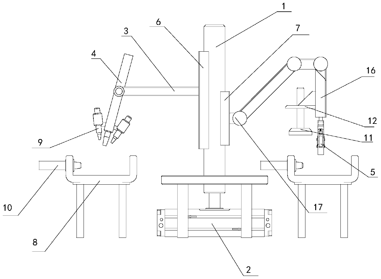
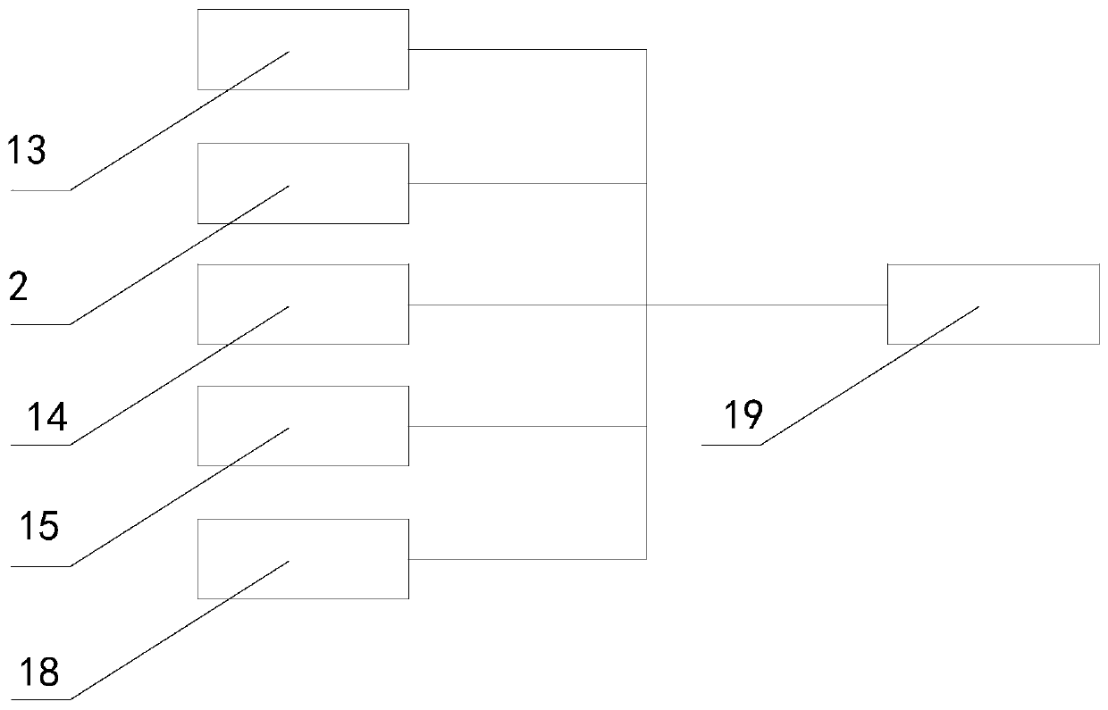
The invention discloses an automatic welding device, and belongs to the welding field. The automatic welding device comprises a machine base, a central shaft, a first drive mechanism, a support frame,a welding gun, a mechanical arm, a mechanical hand, a first sliding rail, a second sliding rail, and a workbench, wherein the central shaft is arranged vertically on the machine base; the first drivemechanism is used for driving the central shaft to rotate; the support frame is arranged vertically on the central shaft; the welding gun is articulated on the support frame and is driven to rotate by a second drive mechanism; the mechanical arm is articulated on the central shaft; the mechanical hand is arranged on the mechanical arm, and is used for clamping a workpiece to be clamped; the firstsliding rail and the second sliding rail are fixedly arranged on the central shaft; the support frame is in slip connection with the central shaft through the first sliding rail; the mechanical arm is in slip connection with the central shaft through the second sliding rail; and the workbench is arranged on the machine base and is used for placing the workpiece. Compared with the prior art, the automatic welding device has higher working efficiency.

Description

technical field [0001] The invention relates to the field of welding, in particular to an automatic welding device. Background technique [0002] Welding is a common metal process that fuses materials at high temperatures to hold two parts together. For some processes with high welding requirements, multiple solder joints are required between two parts, and repeated welding is required. In order to save manpower, a variety of automatic welding devices have appeared on the market to automatically weld the joints of the workpieces. [0003] However, the existing welding devices have poor degrees of freedom, and it is difficult to realize fast loading and unloading, requiring manual positioning and handling. For large parts, manual handling is obviously labor-intensive. On the other hand, in some welding equipment, parts need to be transferred between the discharge channel and the feed channel. This method is not suitable for welding large parts, and requires high-power power...

Claims


Application Information

Patent Timeline
Patent Type & Authority Applications(China)
IPC IPC(8): B23K37/02B23K37/00
CPCB23K37/00B23K37/0252
Inventor 刘爱军钟誉
Owner 深圳市德洋实验设备有限公司
Learn More