A kind of slime mold equipment

A strain and wood strip technology, which is applied in botany equipment and methods, horticulture, agriculture, etc., can solve the problems of reduced work efficiency, easy sore hands, uneven strains, etc., and achieve the effect of avoiding waste and avoiding sore hands

Active Publication Date: 2021-11-05
山东沂南园区开发建设有限公司
View PDF6 Cites 0 Cited by
  • Summary
  • Abstract
  • Description
  • Claims
  • Application Information

AI Technical Summary

Problems solved by technology

[0005] In order to overcome the shortcoming that it is necessary to push the wooden sticks to move and stick the bacteria by hand, the hand is easy to be sore, which leads to a decrease in work efficiency, and it is easy to cause uneven bacteria sticking on the wooden sticks. Therefore, the technical problem of the present invention is: to provide a method that can Instead of artificially sticking the bacteria on the wooden strips, the work efficiency is high, and the bacteria can evenly stick to the wooden sticks.

Method used


Image

  • A kind of slime mold equipment
  • A kind of slime mold equipment
  • A kind of slime mold equipment

Examples


Embodiment 1

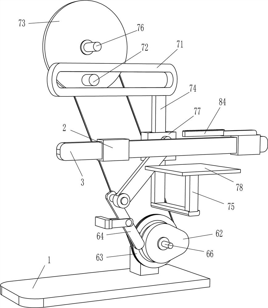
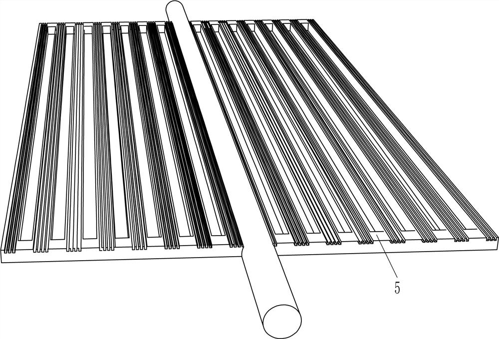
[0022] refer to Figure 1-Figure 4 , a kind of stick mold equipment, including installation shell 1, guide sleeve 2, movable plate 3, placement frame 4, placement plate 5, drive mechanism 6 and push mechanism 7, the left and right sides of the middle part of the rear side of the installation shell 1 All are fixedly connected with guide sleeves 2, and a movable plate 3 is slidably arranged between the guide sleeves 2 on the left and right sides. A placement plate 5 is fixedly connected between the left side of the upper part of the side, and the lower side of the installation shell 1 is provided with a drive mechanism 6, which is fixedly connected to the rear side of the movable plate 3, and the upper side of the installation shell 1 is provided with a drive mechanism 6. There is a pushing mechanism 7, which is connected and matched with the placement frame 4, and the pushed mechanism 7 is also connected and matched with the driving mechanism 6.

[0023] The drive mechanism 6 ...

Embodiment 2

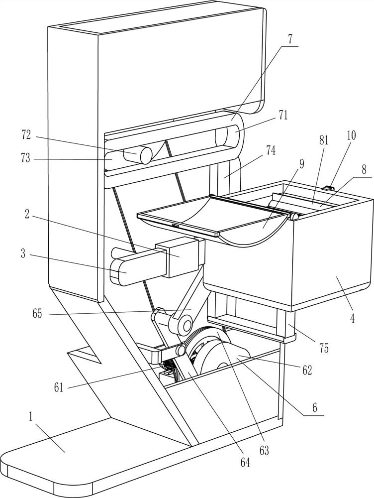
[0029] refer to Figure 1-Figure 3 Compared with Embodiment 1, the main difference of this embodiment is that in this embodiment, a turning mechanism 8 is also included. Rotating between the upper side of the right part of the side is connected with a rotating rod 82, the rear end of the rotating rod 82 is fixedly connected with a gear 83, the rotating rod 82 is equipped with agitating blades 81, and the agitating blades 81 are located in the placement frame 4, and the right guide sleeve 2. A rack 84 is affixed to the top, and the rack 84 is located below the gear 83 and engages with it.

[0030] When the driving motor 61 is started, the left and right movement of the placement frame 4 also drives the gear 83 to move left and right, and the left and right movement of the gear 83 rotates alternately through the rack 84. The forward and reverse rotation of the gear 83 drives the rotating rod 82 to rotate alternately. Alternate forward and reverse rotation drives the stirring bl...


PUM


Abstract

The invention relates to a strain equipment, in particular to a sticky mold spawn equipment. The technical problem is how to design a kind of wooden rod sticky bacteria seed equipment that can replace manual bacteria sticking on wooden sticks, has high work efficiency, and bacteria can evenly stick on wooden sticks. A device for sticky slime bacteria, including a mounting shell, a guide sleeve is symmetrically installed in the middle of one side of the mounting shell, and a movable plate is slidably connected between the two guide sleeves, so that the bacteria Such a placement frame is installed on the side of the movable plate away from the installation shell. In the present invention, by pouring an appropriate amount of bacteria into the placement frame, placing the wooden strips on the placement board, and starting the drive motor, the pushing plate can push the bacteria to the wooden strips, so that the bacteria stick to the wooden strips On the top, and the bacteria are moved left and right through the placement frame, which can make the bacteria stick to the wooden strips more evenly, without manually sticking the bacteria to the wooden strips, avoiding sore hands and reducing work efficiency.

Description

technical field [0001] The invention relates to a strain equipment, in particular to a sticky mold spawn equipment. Background technique [0002] Bacteria: Microorganisms used in the fermentation process as living cell catalysts, including bacteria, actinomycetes, yeasts and molds. It comes from a large number of microorganisms in nature, from which useful strains are isolated and screened, and then improved and stored for production. In the cultivation of fungus, an appropriate amount of strains is stuck on the wooden strips, and then cultivated for a long time , making the bacteria grow into fungus. [0003] At present, most of the strains are manually glued to the wooden strips. First, people need to put the wooden strips on the strains, and then use both hands to push the wooden strips to roll back and forth on the strains, so that the strains can stick to the wood. On the strip, after such a long time, people's hands are prone to soreness, which leads to a decrease in...

Claims


Application Information

Patent Timeline
Patent Type & Authority Patents(China)
IPC IPC(8): A01G18/50
CPCA01G18/50
Inventor 赵养古
Owner 山东沂南园区开发建设有限公司
Why Eureka
Try Eureka