
Hub switching structure

A transfer and hub technology, applied in the field of mobile robots, can solve problems such as not being well satisfied

Inactive Publication Date: 2020-07-07
SHENYANG SIASUN ROBOT & AUTOMATION
View PDF7 Cites 0 Cited by
  • Summary
  • Abstract
  • Description
  • Claims
  • Application Information

AI Technical Summary

Problems solved by technology

Therefore, the current structural form can no longer meet the needs of modern mobile robots.

Method used


Image

  • Hub switching structure
  • Hub switching structure
  • Hub switching structure

Examples


Embodiment Construction

[0023] Embodiments of the present invention are described in detail below, examples of which are shown in the drawings, wherein the same or similar reference numerals designate the same or similar elements or elements having the same or similar functions throughout. The embodiments described below by referring to the figures are exemplary and are intended to explain the present invention and should not be construed as limiting the present invention.

[0024] In describing the present invention, it should be understood that the terms "center", "longitudinal", "transverse", "length", "width", "thickness", "upper", "lower", "front", " The orientation or positional relationship indicated by "rear", "left", "right", "vertical", "horizontal", "top", "bottom", "inner" and "outer" are based on the orientation or position shown in the drawings The positional relationship is only for the convenience of describing the present invention and simplifying the description, but does not indica...


PUM


Abstract

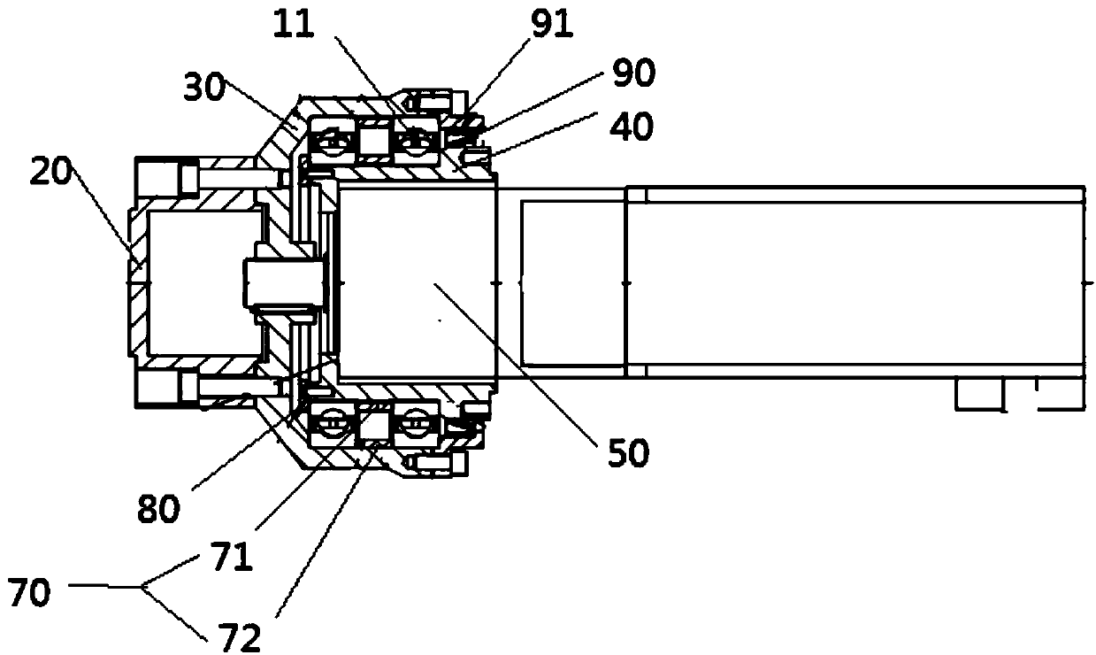
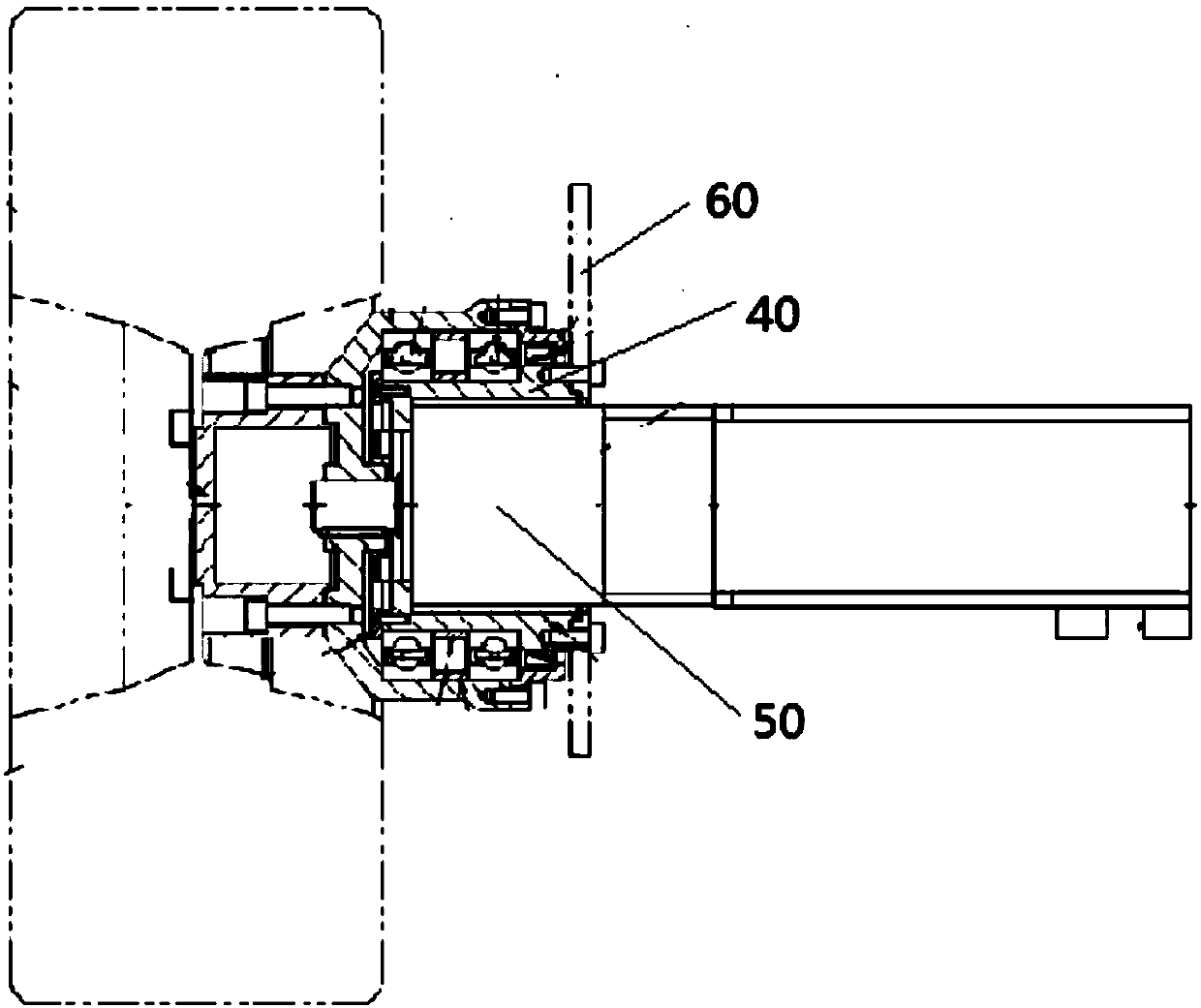
The invention provides a hub switching structure. The hub switching structure comprises a tire connecting piece, a rotating flange, a bearing assembly, a flange supporting shaft and a driving unit, wherein the flange supporting shaft is internally provided with an accommodating space, and the driving unit is installed in the accommodating space; an output shaft of the driving unit is fixedly connected with the rotating flange so as to drive the rotating flange to rotate around the flange supporting shaft; and the tire connecting piece is fixedly connected with the rotating flange. According tothe hub switching structure provided by the invention, the driving unit can directly drive wheels to rotate, and the hub switching structure can adapt to the wheels with different diameters.

Description

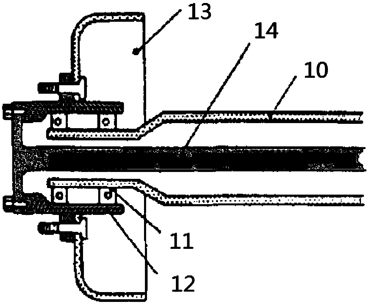
technical field [0001] The invention relates to the field of mobile robots, in particular to a hub transfer structure used in the field of mobile robots. Background technique [0002] There are many kinds of wheel hub transfer structures now, and the basic form is: the axle housing 10 is connected with the vehicle frame through the suspension, and the two ends of the axle housing 10 are connected with the wheels 13 through the hub 12, as shown in the attached figure 1 As shown, the end of the axle housing 10 is sleeved with a bearing assembly 11, the outside of the bearing assembly 11 is connected to the hub 12, the hub 12 rotates around the end of the axle housing 10 through the bearing assembly 11, and the wheels 13 or tires are mounted on the hub 12 superior. At the same time, the motor inside the vehicle is fixedly connected to the hub 12 through the axle 14 to drive the hub 12 to rotate around the end of the axle housing 10 . [0003] This connection mode is very limi...

Claims


Application Information

Patent Timeline
IPC IPC(8): B60K7/00
CPCB60K7/0007B60K2007/0092
Inventor 徐方尹红光何元一李刚李加平武桐
Owner SHENYANG SIASUN ROBOT & AUTOMATION
Learn More