
Device for controlling a stretch-reducing mill

A technology of tension reduction and rolling mill, which is applied in the direction of driving device, rolling mill control device, tail end control, etc. for metal rolling mills. It can solve the problems of not considering the influence, the influence of adjustment results, and the inability to adapt the use time and effect duration and other issues to achieve the effect of reducing the burden

Inactive Publication Date: 2020-07-03
SMS GRP GMBH
View PDF13 Cites 0 Cited by
  • Summary
  • Abstract
  • Description
  • Claims
  • Application Information

AI Technical Summary

Problems solved by technology

But the use time and duration of the effect cannot be adapted
However, both have a high influence on the regulation outcome
Furthermore, the effect of the entering tube is not considered
Also no combinations of multiple rolls are listed to minimize the effects of measurement errors or outliers
[0011] A disadvantage of the prior art is that the rolling mill operator has to make corrective settings on the CEC during actual operation mostly or at least at the start of the rolling campaign

Method used


Image

  • Device for controlling a stretch-reducing mill

Examples


Embodiment Construction

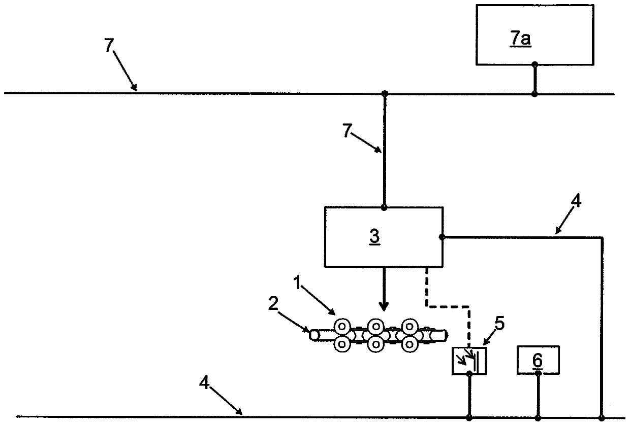
[0032] The tension reducing mill comprises a plurality of rolls in a rolling stand 1 driven by adjustable motors. In this case, the tension reduction of the rolling stock 2 takes place by targeted control of the motors with different rotational speeds, so that the rolling stock is placed under tensile stress between the rollers.

[0033] The motor is powered by a programmable controller (SPS) 3 . The SPS 3 takes over the query and / or calculation of the rotational speed of the motor during the rolling process.

[0034] The SPS 3 is connected to the sensors 5 , 6 via a network 4 in the form of a fieldbus system, so that measured values ​​flow directly into the SPS. The sensor 5 is here by way of example a position sensor, for example in the form of a light barrier. The sensors 6 determine further measured values ​​for monitoring the rolling process, in particular the diameter, wall thickness and temperature of the rolling stock.

[0035] Furthermore, the SPS 3 can communicate...


PUM


Abstract

The invention relates to a method for controlling a stretch-reducing mill in which tube ends of stretched tubes are optimised by controlling one or more motors of the stretch-reducing mill (1), said method comprising at least one wall thickness measurement on the discharge side and automatic adaptation of the magnitude of the change in the speed of the motors to the tube wall thickness profile, wherein the development over time of the changes in the speed of individual or all the motors is adapted automatically on the basis of the tube wall thickness measurement values.

Description

technical field [0001] The invention relates to a method for controlling a tension reducing mill according to the preamble of claim 1 . Background technique [0002] When performing tension reduction of the tube, the tube wall thickness is thickened or upset at the ends of the tube due to the process compared to the middle part of the tube. This is because the front or rear tube end does not reach the center of the tube due to the missing rolling stand running forward or backward in the conveying direction, which is engaged on the rolling stock. Sections otherwise obtained in rolled longitudinal stretch. Tube sections that are thicker than the permissible wall thickness tolerances are therefore a loss of production and must be cut off. [0003] In addition, especially in tension reducing mills in seamless tube plants, the parent tubes or tube blanks used can have an upset wall thickness at the ends, for example due to tool wear in the prefabricated assembly. This upsettin...

Claims


Application Information

Patent Timeline
Patent Type & Authority Applications(China)
IPC IPC(8): B21B37/78
CPCB21B17/14B21B37/72B21B37/78B21B2261/10B21B2275/04
Inventor A·古尔
Owner SMS GRP GMBH
Learn More