Telescopic cutter
A technology of knives and blades, which is applied in fish processing hand tools, fish processing, slaughtering, etc., can solve the problem that it cannot be applied to fish of different sizes, and achieve the effect of improving the scope of application
- Summary
- Abstract
- Description
- Claims
- Application Information
AI Technical Summary
Problems solved by technology
Method used
Image
Examples
Embodiment 1
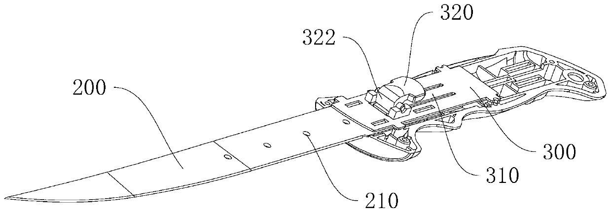
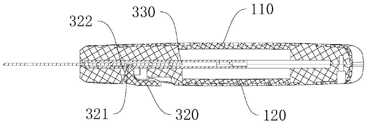
[0031] This embodiment provides a telescopic cutter, which can be used as a fish knife for cutting fish. like Figure 1-6 As shown, the tool includes a handle 100 and a blade 200, the handle 100 includes a first housing 110 and a second housing 120 that are detachably connected, the blade 200 is clamped between the first housing 110 and the second housing 120, and the blade 200 has a plurality of limiting openings 210 arranged horizontally, and a plurality of limiting openings 210 refers to two or more, for example, five. The limiting opening 210 can be a groove structure or a hole-like structure. The hole-like structure adopted in this embodiment means that a plurality of holes are opened in the middle of the blade 200 as the limiting opening 210 . The handle 100 is provided with a limit structure corresponding to the limit port 210, and the limit structure includes a lock position and an unlock position; when the limit structure is in the lock position, the blade 200 is fix...
Embodiment 2
[0037] The difference between this embodiment and the first embodiment mainly lies in the limiting structure.
[0038] Specifically, as Figure 9-10 As shown, the limiting structure includes a button 410 protruding from the handle 100, and the button 410 is provided with a locking bar 420 that penetrates the handle 100. The locking bar 420 has a locking block 430; when the limiting structure is in the locked position, the locking block 430 and the limiting opening 210 are staggered; when the limiting structure is in the unlocking position, the locking block 430 is inserted into the limiting opening 210 . An elastic member 140 is disposed between the locking bar 420 and the handle 100 , and the elastic member 140 provides elastic force for the locking bar 420 so that the locking block 430 fits into the limiting opening 210 . Wherein the elastic member 140 is a spring.
[0039] Press the button 410, and the lock bar 420 moves against the elastic force of the elastic member 140...
Embodiment 3
[0042] The difference between this embodiment and the first embodiment mainly lies in the limiting structure.
[0043] Specifically, the limit opening 210 is a limit groove 211 with an opening facing upwards, and there are four limit grooves 211. The limit structure includes a lock 510 hinged on the handle 100, and one end of the lock 510 has a lock hook 511. An elastic member 140 is arranged between the member 510 and the handle 100 . The elastic member 140 provides elastic force for the lock member 510 to make the lock hook 511 fit into the limiting groove 211 . Wherein the elastic member 140 is a shrapnel.
[0044] The lock 510 can be partly exposed to the handle 100 for operation. For example, the rear section of the hinge joint between the lock 510 and the handle 100 is exposed to the handle 100. When the rear section is pressed, the lock 510 overcomes the elastic member 140 and swings so that there is a lock hook 511. One end is upturned, and the locking hook 511 breaks...
PUM
 Abstract
Description
Claims
Application Information
 - R&D
- Intellectual Property
- Life Sciences
- Materials
- Tech Scout
- Unparalleled Data Quality
- Higher Quality Content
- 60% Fewer Hallucinations
Browse by: Latest US Patents, China's latest patents, Technical Efficacy Thesaurus, Application Domain, Technology Topic, Popular Technical Reports.
© 2025 PatSnap. All rights reserved.Legal|Privacy policy|Modern Slavery Act Transparency Statement|Sitemap|About US| Contact US: help@patsnap.com


