
Air conditioner indoor unit

A technology for air-conditioning indoor units and cabinets, applied in air-conditioning systems, space heating and ventilation, space heating and ventilation details, etc., can solve problems such as affecting air intake at the air inlet, condensed water dripping, burns or electric shocks, etc., to achieve Improve user experience, facilitate discharge, and simple structure

Pending Publication Date: 2020-06-30
QINGDAO HAIER AIR CONDITIONER GENERAL CORP LTD +1
View PDF0 Cites 0 Cited by
  • Summary
  • Abstract
  • Description
  • Claims
  • Application Information

AI Technical Summary

Problems solved by technology

If a water tray is installed under the evaporator, the water tray will hinder the flow of air and affect the air intake at the air inlet; if no water tray is installed, the condensed water generated by the evaporator will drip through the air inlet, which will bring troubles to users
In the prior art, some air-conditioning indoor units that require bottom air intake change the position of the evaporator near the air outlet in order to avoid dripping of condensed water. potential safety hazards such as electric shock), and the condensed water generated on the evaporator will be blown out with the airflow, affecting the user experience

Method used


Image

  • Air conditioner indoor unit
  • Air conditioner indoor unit
  • Air conditioner indoor unit

Examples


Embodiment Construction

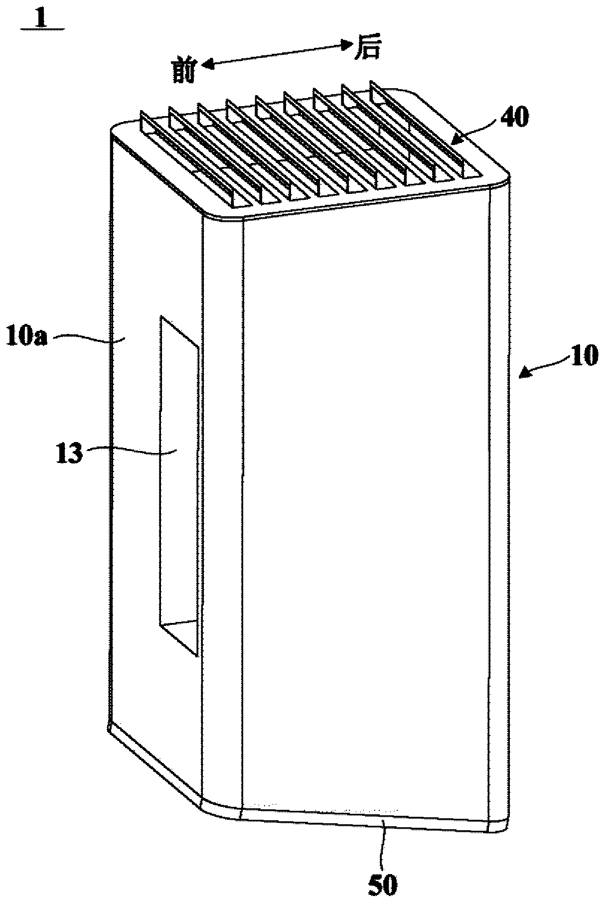
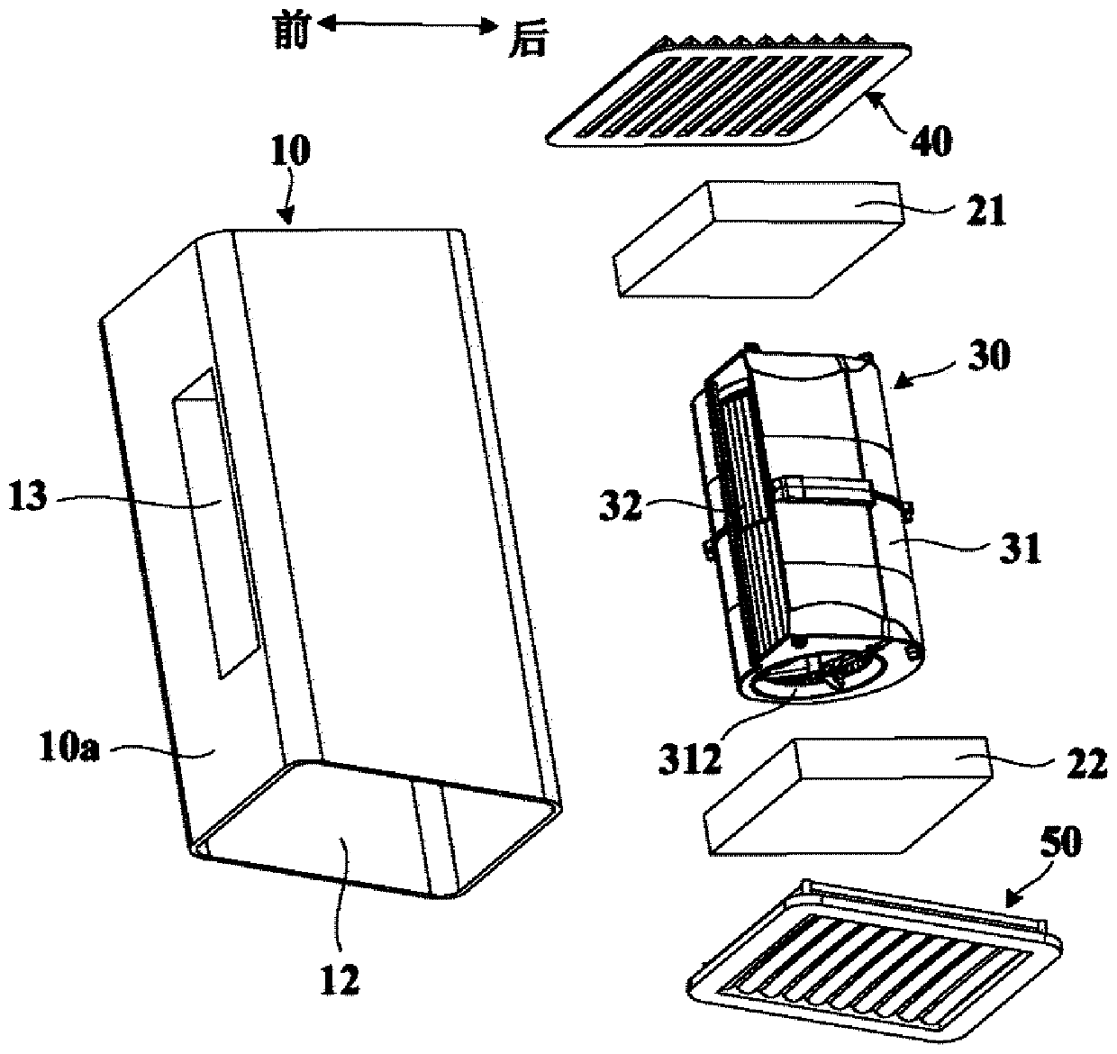
[0037] The invention provides an air conditioner indoor unit, figure 1 is a schematic structural diagram of an air conditioner indoor unit according to an embodiment of the present invention, figure 2 is a schematic exploded view of an air conditioner indoor unit according to an embodiment of the present invention. see figure 1 and figure 2 , the air conditioner indoor unit 1 of the present invention includes a casing 10 and a lower heat exchanger 22 . The casing 10 has a lower air inlet 12 opened at the bottom thereof. Specifically, the lower air inlet 12 may be opened on the bottom surface of the casing 10 . The casing 10 is used to hang and be arranged on the wall in the space where it is located, and does not occupy the floor space in the room, and the space below it close to the ground can be released for users to store items, etc., so as to make better use of the indoor space. The lower heat exchanger 22 is horizontally disposed in the casing 10 and located above ...


PUM


Abstract

The invention provides an air conditioner indoor unit which comprises a shell and a heat exchanger. The shell is provided with a lower air inlet formed in the bottom. The heat exchanger is arranged inside the shell in the transverse direction and located above the lower air inlet. A lower air inlet grating is arranged at the lower air inlet. The lower air inlet grating comprises at least two layers of grating plates stacked in the vertical direction in a spaced mode. Each layer of grating plate comprises a plurality of lower gratings arranged in a spaced mode so as to form lower grating holesthrough which airflow passes between two adjacent lower gratings. The projection of each lower grating hole of each layer of grating plate falls into the projection of the lower grating of the other layers of grating plates inside the horizontal plane. Condensate water generated on the heat exchanger can fall down on the lower gratings and cannot drip outside the shell through any one lower grating hole, and therefore the using experience of users is improved. The lower air inlet grating integrates dual functions of a traditional air inlet grating and a water pan on the premise of not affecting the air inlet amount, and the structure is quite simple.

Description

technical field [0001] The invention relates to an air conditioner, in particular to an air conditioner indoor unit. Background technique [0002] The air inlet of the air conditioner indoor unit is usually arranged on the top of the casing. In order to expand the air intake, some air-conditioning indoor units are also provided with air inlets on the side of the casing, but rarely the air inlets are arranged at the bottom of the casing. This is because, in order to comply with safety regulations and meet heat exchange requirements, the evaporator needs to be installed in the casing adjacent to the air inlet. If the air inlet is set at the bottom of the casing, the evaporator is located above the air inlet. If a water tray is installed under the evaporator, the water tray will block the flow of air and affect the air intake at the air inlet; if no water tray is installed, the condensed water produced by the evaporator will drip through the air inlet, causing troubles to user...

Claims


Application Information

Patent Timeline
Patent Type & Authority Applications(China)
IPC IPC(8): F24F1/0063F24F13/20F24F13/22F24F13/08
CPCF24F1/0063F24F13/082F24F13/20F24F13/222
Inventor 孙婷赫明亮王佳林陈吉存李进超
Owner QINGDAO HAIER AIR CONDITIONER GENERAL CORP LTD
Learn More