
Fabricated building outer wall construction operation device

A kind of building exterior wall, prefabricated technology, applied in the direction of building, building structure, house structure support, etc., can solve the problem of high labor intensity of artificial pulling, and achieve the effect of reducing labor intensity

Inactive Publication Date: 2020-06-30
宁夏绿筑集成科技有限公司
View PDF8 Cites 0 Cited by
  • Summary
  • Abstract
  • Description
  • Claims
  • Application Information

AI Technical Summary

Problems solved by technology

[0003] The purpose of the present invention is to solve the disadvantages of manual lifting labor intensity

Method used


Image

  • Fabricated building outer wall construction operation device
  • Fabricated building outer wall construction operation device
  • Fabricated building outer wall construction operation device

Examples


Example Embodiment

[0022] Example 1

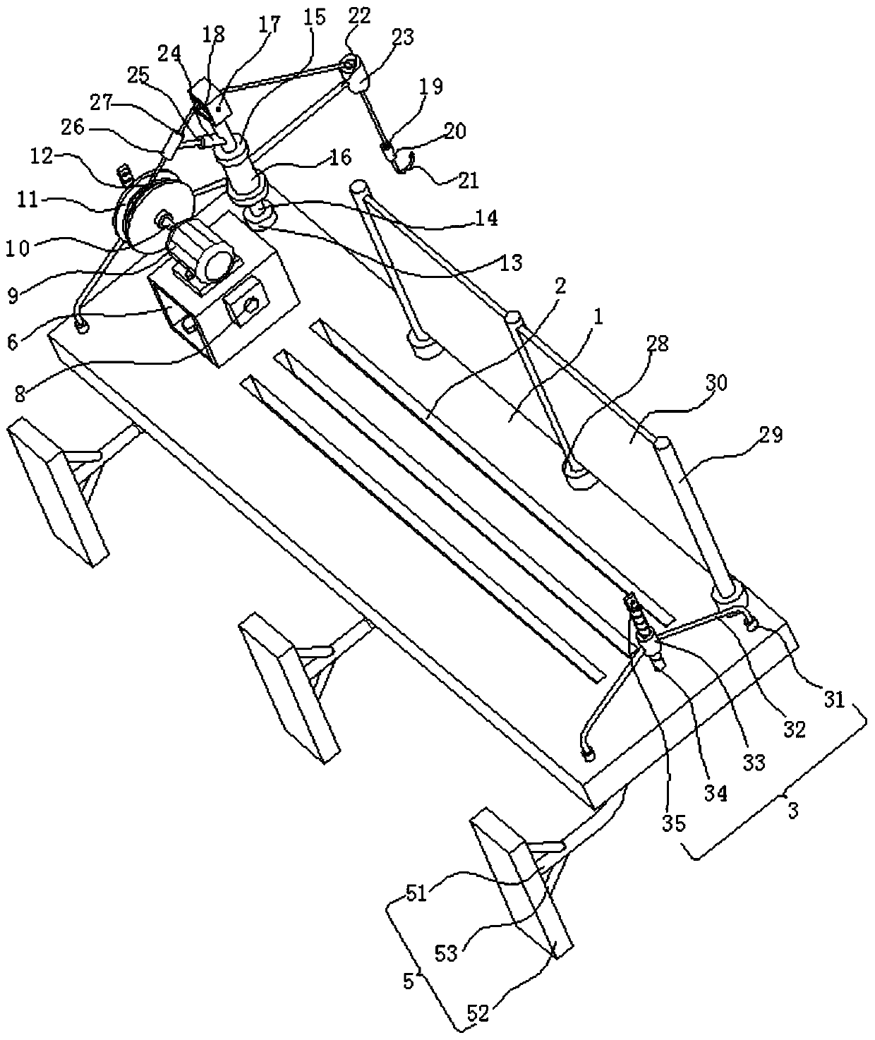
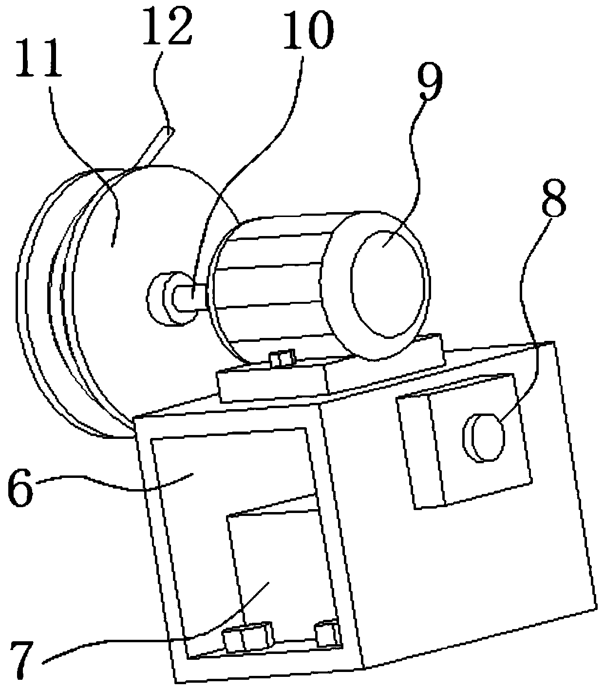
[0023] refer to Figure 1-4 , an assembly type building exterior wall construction operation device, including a support plate 1, a plurality of strip holes 2 are opened on the support plate 1, and the function of the strip holes 2 is to facilitate the discharge of the sundries on the support plate 1, and the support plate The upper end of 1 is fixedly connected with a connecting frame on both sides. The function of the connecting frame is to connect with the external pulling mechanism to control the height of the support plate 1. The bottom end of the support plate 1 is fixedly connected with a number of second fixing seats 4. Supporting feet 5 are fixedly connected to each of the second fixing bases 4 . The function of the supporting feet 5 is to contact the wall, so that the support plate 1 will not tip over. The upper end of the support plate 1 is fixedly connected with a first fixing frame 6 .

[0024] A battery block 7 is fixedly connected in the firs...

Example Embodiment

[0027] Example 2

[0028] refer to figure 1 , as another preferred embodiment of the present invention, the difference from Embodiment 1 is that the connecting frame includes two first fixing bases 31 , the function of the first fixing bases 31 is to fix the first fixing rod 32 , and each first fixing base 31 are fixedly connected with a first fixing rod 32, one end of each first fixing rod 32 is fixedly connected with a threaded sleeve 33, the function of the threaded sleeve 33 is to connect the threaded rod 34, and the threaded rod 34 is connected to the threaded sleeve 33, The upper end of the threaded rod 34 is provided with a through hole 35, and the function of the through hole 35 is to connect an external pulling device.

Example Embodiment

[0029] Example 3

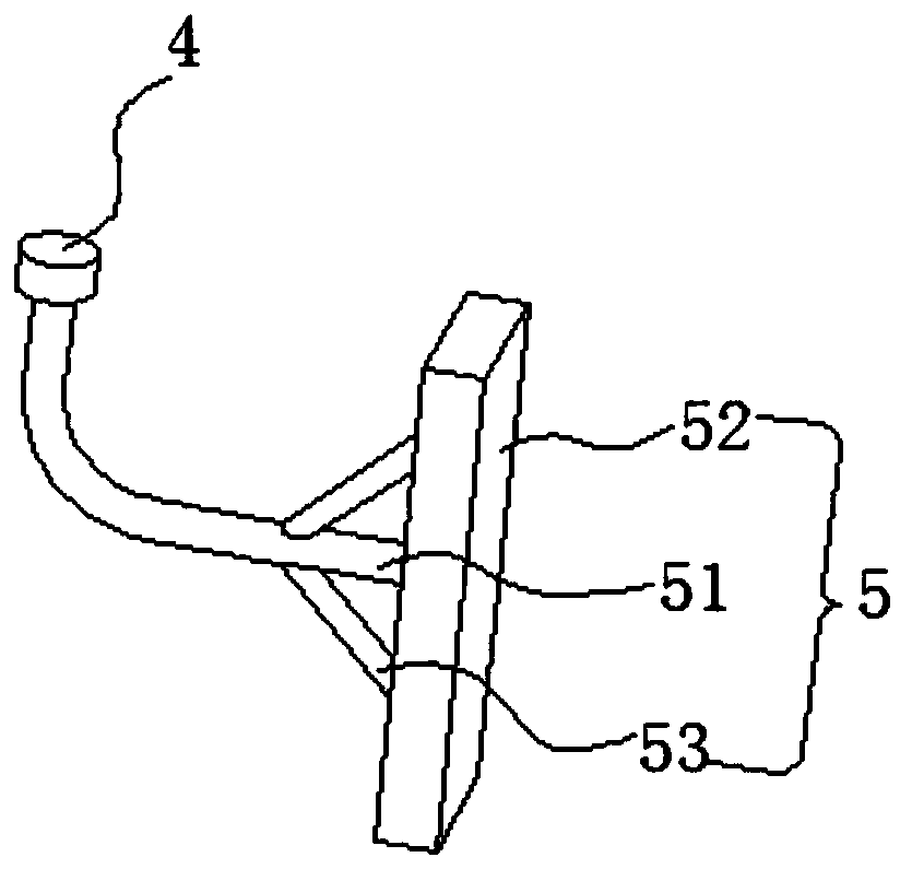
[0030] refer to Figure 1-2 , as another preferred embodiment of the present invention, the difference from Embodiment 1 is that the support foot 5 includes a second fixing rod 51, the second fixing rod 51 is connected to the second fixing seat 4, and one end of the second fixing rod 51 is fixedly connected There is a fixed plate 52, the function of the fixed plate 52 is to contact the wall to prevent the support plate 1 from overturning, the fixed plate 52 is connected with a reinforcing rod 53, and one end of the reinforcing rod 53 is connected to the second fixed rod 51.


PUM


Abstract

The invention relates to the technical field of buildings, in particular to a fabricated building outer wall construction operation device. The device comprises a supporting plate, the bottom end of the supporting plate is fixedly connected with a plurality of second fixed bases, each second fixed base is fixedly connected with a supporting leg, and an upper end of the supporting plate is fixedlyconnected with a third fixed base; the third fixed base is fixedly connected with a third fixed rod, the third fixed rod is fixedly connected with two limiting blocks, the third fixed rod is rotationally connected with a rotating pipe which is located between the two limiting blocks; one side of the rotating pipe is fixedly connected with a steering mechanism, and the upper end of the third fixedrod is fixedly connected with a reversing mechanism; one end of a steel rope is fixedly connected with a fixed heat through the steering mechanism and the reversing mechanism, and the fixed head is connected with a hook component. Barreled mixture is extracted after the motor is powered on and started, the mixture does not need to be pulled manually, and the labor intensity is reduced.

Description

technical field [0001] The invention relates to the field of building technology, in particular to a device for construction of an exterior wall of a prefabricated building. Background technique [0002] The exterior wall of the building is the boundary wall that makes the whole building form indoors and outdoors. The exterior wall of the building is used to enclose the building. Scaffolding refers to various supports erected on the construction site for workers to operate and solve vertical and horizontal transportation. Assembled walls After the body is assembled, there is a gap between the wall and the wall, and the gap needs to be sealed manually with the mixture. However, the building is generally high, and the mixture needs to be manually pulled up to the springboard, which is labor-intensive. Contents of the invention [0003] The purpose of the present invention is to solve the disadvantage of high labor intensity of manual lifting in the prior art, and propose a d...

Claims


Application Information

Patent Timeline
IPC IPC(8): E04G3/28E04G3/32E04G5/00E04G5/08E04G5/14
CPCE04G3/28E04G3/325E04G5/00E04G5/08E04G5/14E04G2003/286E04G2005/008
Inventor 马海华周坤王兴马惠丽张鹏飞
Owner 宁夏绿筑集成科技有限公司
Learn More