
Ventilation cabinet

A technology for fume hoods and ventilation pipes, applied in the field of fume hoods, which can solve problems affecting the operation of experimenters and dust dispersal, and achieve the effects of increasing dust removal efficiency, reducing dust, and preventing dust.

Pending Publication Date: 2020-06-30
珠海科艺普实验室设备有限公司
View PDF0 Cites 0 Cited by
  • Summary
  • Abstract
  • Description
  • Claims
  • Application Information

AI Technical Summary

Problems solved by technology

[0003] In the past, the fume hood sucked and discharged the harmful gas through the deflector installed inside the cabinet and the negative pressure fan installed on the top of the cabinet. There is a gap between the two deflectors, and the gap forms an air inlet. Since there are multiple air inlets, it is more convenient to absorb harmful gases. However, when dust is absorbed, multiple air inlets cause the dust to scatter around, which affects the experimenters. operate

Method used


Image

  • Ventilation cabinet
  • Ventilation cabinet
  • Ventilation cabinet

Examples


Embodiment Construction

[0026] Embodiments of the present invention are described in detail below, examples of which are shown in the drawings, wherein the same or similar reference numerals designate the same or similar elements or elements having the same or similar functions throughout. The embodiments described below by referring to the figures are exemplary only for explaining the present invention and should not be construed as limiting the present invention.

[0027] In the description of the present invention, it should be understood that the orientation descriptions, such as up, down, front, back, left, right, etc. indicated orientations or positional relationships are based on the orientations or positional relationships shown in the drawings, and are only In order to facilitate the description of the present invention and simplify the description, it does not indicate or imply that the device or element referred to must have a specific orientation, be constructed and operated in a specific ...


PUM


Abstract

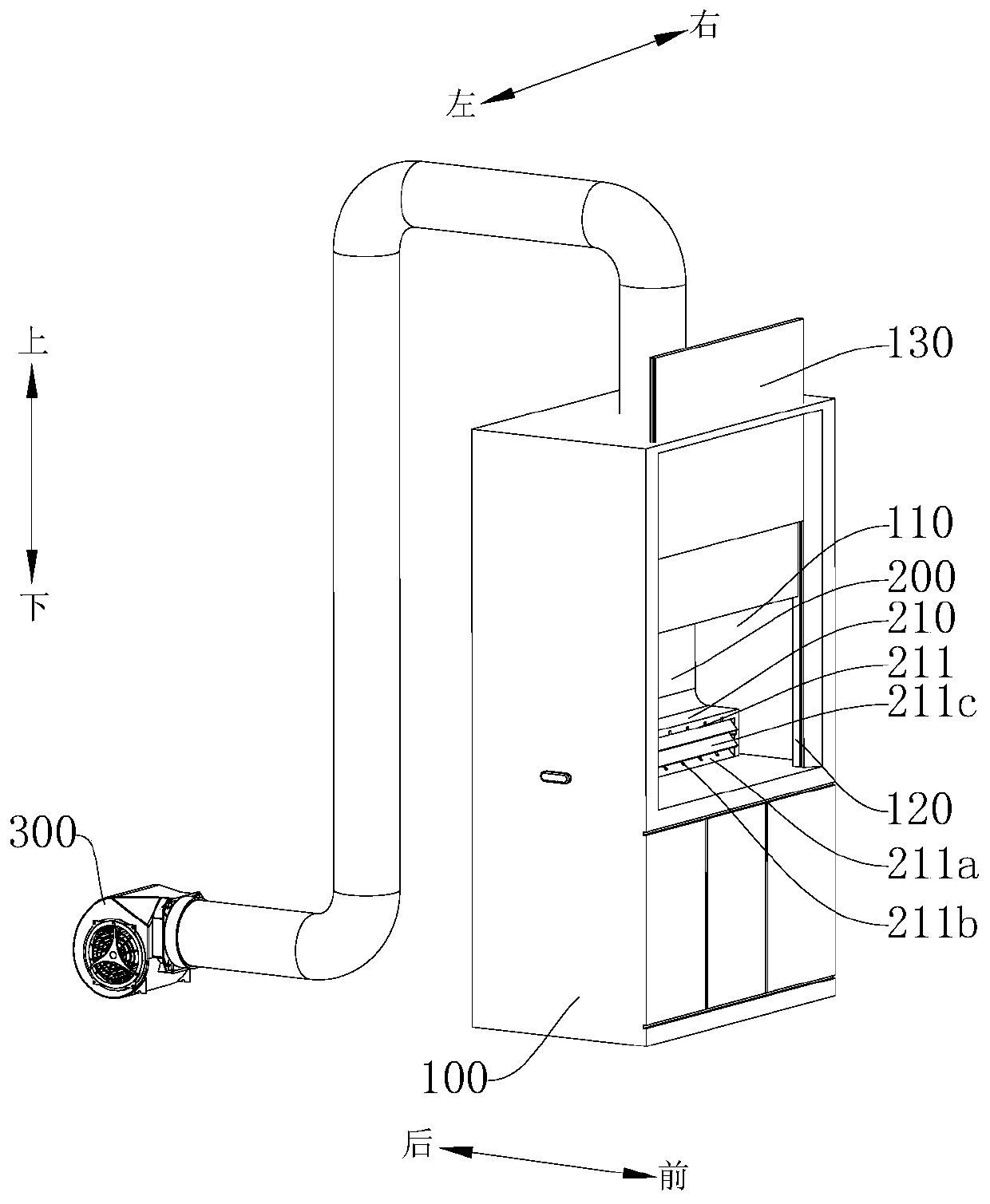
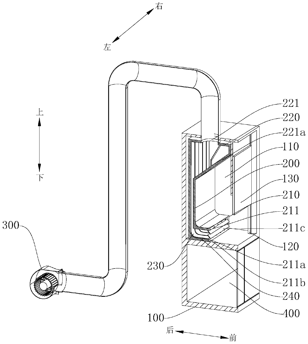
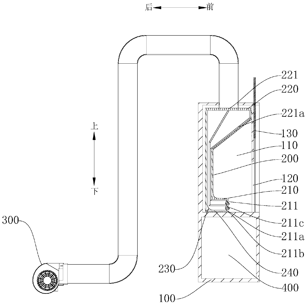
The invention discloses a ventilation cabinet. The ventilation cabinet comprises a cabinet body and a ventilation pipe, wherein the cabinet body is provided with an operation cavity; the ventilation pipe is arranged in the operation cavity and comprises an air inlet section, a flow guide section and an air outlet section; the bottom surface of the air inlet section is tightly attached to the innerbottom surface of the operation cavity; the rear side surface of the flow guide section is tightly attached to the inner side wall of the rear end of the operation cavity; the upper end surface of the air outlet section is tightly attached to the inner side wall of the upper end of the operation cavity; the left side and the right side of the ventilation pipe are tightly attached to the left inner side wall and the right inner side wall of the operation cavity; an air inlet of the air inlet section faces forwards; and an air outlet of the air outlet section faces upwards. According to the ventilation cabinet, the ventilation pipe is arranged in the ventilation cabinet, so that dust enters from a single inlet, and dust flying in the experiment process is prevented; meanwhile, the side surface of the ventilation pipe is tightly attached to the inner side wall of the operation cavity so as to reserve more operation space, the air inlet faces forwards, so that the shortest stroke of the dust entering the ventilation pipe can be guaranteed, and the dust removal efficiency is improved; and the bottom surface of the air inlet section is tightly attached to the bottom surface of the operation cavity so that the dust can enter from the bottom surface of the operation cavity, and the dust is prevented from flying high.

Description

technical field [0001] The invention relates to the technical field of experimental equipment, in particular to a fume hood. Background technique [0002] When conducting experiments in the laboratory, harmful gases are often generated during the experiment. In order to prevent the harmful gases from harming the human body, it is necessary to discharge the harmful gases. The laboratory often uses a fume hood to discharge the harmful gases generated during the experiment. [0003] In the past, the fume hood sucked and discharged the harmful gas through the deflector installed inside the cabinet and the negative pressure fan installed on the top of the cabinet. There is a gap between the two deflectors, and the gap forms an air inlet. Since there are multiple air inlets, it is more convenient to absorb harmful gases. However, when dust is absorbed, multiple air inlets cause the dust to scatter around, which affects the experimenters. operate. Contents of the invention [0...

Claims


Application Information

Patent Timeline
IPC IPC(8): B08B15/02
CPCB08B15/023
Inventor 陈坚生陈有荣
Owner 珠海科艺普实验室设备有限公司
Learn More