
Drill hole inside secondary grouting leaking stoppage device

A secondary grouting and in-drilling technology, applied in safety devices, earthwork drilling, gas discharge, etc., can solve the problems of high labor intensity, high cost, inconvenient operation, etc., and improve the concentration and purity of gas drainage Quantity, increase the concentration of gas drainage, and ensure the effect of grouting

Pending Publication Date: 2020-06-23
YUWU COAL CO LTD OF SHANXI LUAN GRP +1
View PDF0 Cites 5 Cited by
  • Summary
  • Abstract
  • Description
  • Claims
  • Application Information

AI Technical Summary

Problems solved by technology

[0007] At present, the existing sealing technologies, such as hole sealing with hole sealer and capsule hole sealing, have certain shortcomings. Among them, the hole sealing device of the hole sealer is relatively heavy and inconvenient to operate. The hole sealing device of the hole sealer is used on the side of the coal seam roadway Because the shape of the hole is difficult to maintain a regular circle and the hole wall is broken, the sealing effect is often not good, and the quality of the hole is not easy to guarantee, so it is generally only suitable for temporary extraction and sealing; the capsule hole sealing device is laborious to use. High strength, relatively expensive, almost useless to plug the development and expansion of cracks

Method used


Image

  • Drill hole inside secondary grouting leaking stoppage device
  • Drill hole inside secondary grouting leaking stoppage device
  • Drill hole inside secondary grouting leaking stoppage device

Examples


Embodiment Construction

[0020] A specific embodiment of the present invention will be described in detail below with reference to the accompanying drawings, but it should be understood that the protection scope of the present invention is not limited by the specific embodiments.

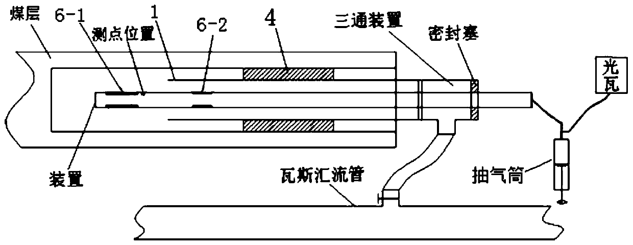
[0021] See Figure 1-Figure 3 The embodiment of the present invention provides a secondary grouting plugging device in a borehole, comprising a plurality of single-section pipes, each single-section pipe includes a gas injection pipe 2 and a grouting pipe 3, and the grouting pipe 3 is sleeved in Inside the gas injection pipe 2, the gap between the two pipes is used as a ventilation channel. A connection piece is fixed between the gas injection pipe 2 and the grouting pipe 3, and the relative position between the two pipes is fixed by the connection piece; the multiple single-section pipes The injection pipes are connected end to end in turn, wherein the grouting pipes 3 of two adjacent single-section pipes are connected, and th...


PUM


Abstract

The invention discloses a drill hole inside secondary grouting leaking stoppage device. The drill hole inside secondary grouting leaking stoppage device comprises an injection pipe composed of a plurality of single-section pipes which are connected in sequence, all the single-section pipes comprise gas injection pipes and grouting pipes, the grouting pipes are arranged inside the gas injection pipes in a sleeved manner, wherein the grouting pipes are connected with the grouting pipes, the gas injection pipes are connected with the gas injection pipes, the inner ends of the multiple mutually-connected gas injection pipes stretch out of the inner end of a gas extraction pipe, get over a fracture zone of a drill hole and are connected with and communicate with an inner end gasbag, the parts,located at the inner end of the gas extraction pipe, of the multiple mutually-connected gas injection pipes are connected with and communicate with an outer end gasbag, the gas extraction pipe and oneend of an inlet of the drill hole are further provided with a sealing body, the ends, located at the drill hole inlet, of the multiple gas injection pipes of the injection pipe are connected with gassupply equipment, and the ends, located at the drill hole inlet, of the multiple grouting pipes of the injection pipe are connected with grouting equipment. By means of the drill hole inside secondary grouting leaking stoppage device, precision grouting with pressure can be performed on the failure drill hole fracture development position, so that the gas extraction failure drill hole extractionfunction is activated and restored, and the gas extraction concentration and purity are increased.

Description

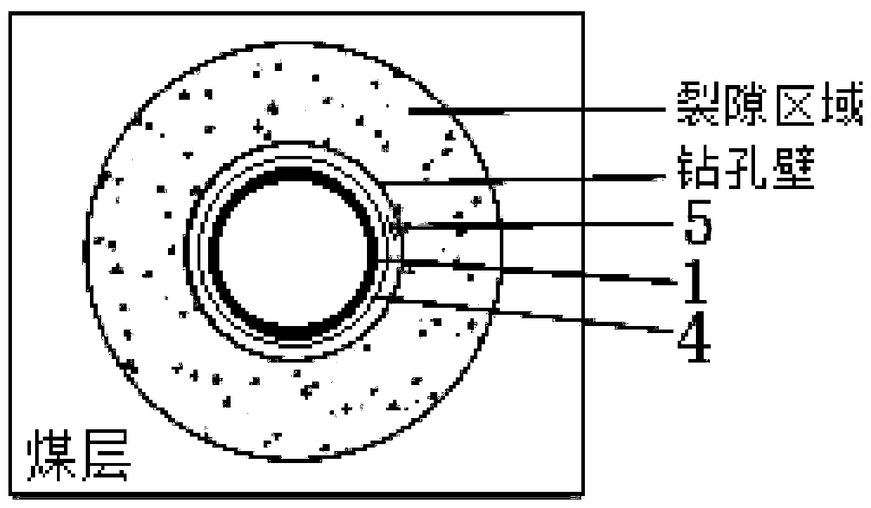
Technical field [0001] The invention relates to the technical field of gas drainage, in particular to a secondary grouting plugging device in a borehole. Background technique [0002] The air leakage of the borehole mainly includes two forms, namely, air leakage inside the hole and air leakage outside the hole. Such as figure 1 As shown, the air leakage in the hole exists in the area between the extraction tube and the borehole wall, including the air leakage of the sealing body material itself and the gap air leakage between the sealing body and the borehole wall. Air leakage outside the hole exists in the fissure area outside the borehole wall. Under the action of negative pressure, outside air enters the coal body through the fissures around the borehole. In order to analyze the reasons for the attenuation of gas drainage concentration more comprehensively, it is necessary to comprehensively consider the leakage inside the hole and the leakage outside the hole, so as to provi...

Claims


Application Information

Patent Timeline
IPC IPC(8): E21F7/00E21B33/13
CPCE21B33/13E21F7/00
Inventor 黄勇张永斌叶川周建伟李云徐宁高保彬陈立伟裴露辉任海涛
Owner YUWU COAL CO LTD OF SHANXI LUAN GRP
Learn More