Eureka AIR delivers breakthrough ideas for toughest innovation challenges, trusted by R&D personnel around the world.

Cutting wheel structure for ultrathin product

A kind of product, the technology of cutter wheel, applied in the field of ultra-thin product cutting cutter wheel structure, can solve the problems of difficult fitting of side ends, large body volume, inconvenient processing and use, etc., to improve compact performance and safety performance, and high controllability Performance, good maneuverability effect

Inactive Publication Date: 2020-06-19
深圳市新世纪拓佳光电技术有限公司
View PDF6 Cites 0 Cited by
  • Summary
  • Abstract
  • Description
  • Claims
  • Application Information

AI Technical Summary

Problems solved by technology

[0004] The purpose of the present invention is to provide an ultra-thin product cutter wheel structure to solve the problem that the existing cutting device proposed in the background technology is not compact enough in its own structure, resulting in too large body volume and a large space occupation, which is not practical enough. Moreover, the storage is not convenient enough, and the structures cannot cooperate with each other, that is, it is difficult to fit the side ends with the bottom, so that it cannot be used as a table, and there is a situation that the processing and use are not convenient enough

Method used

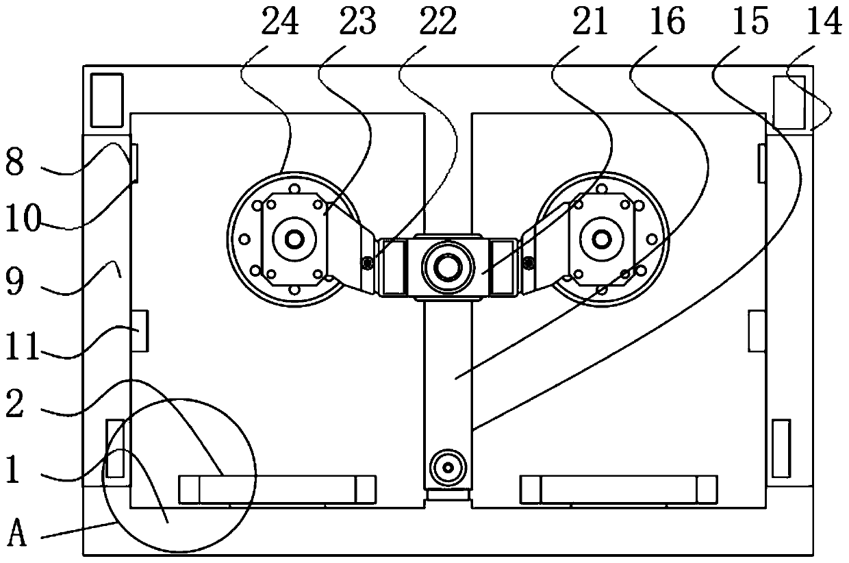
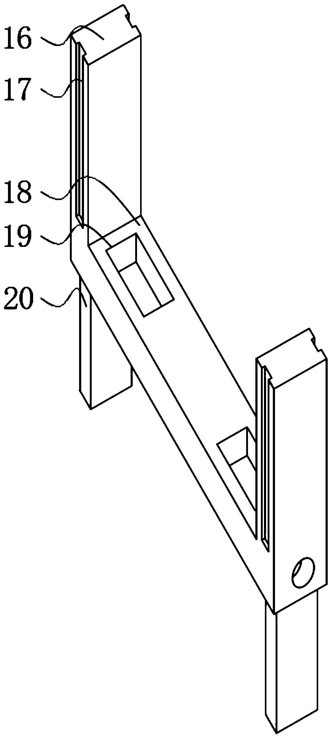
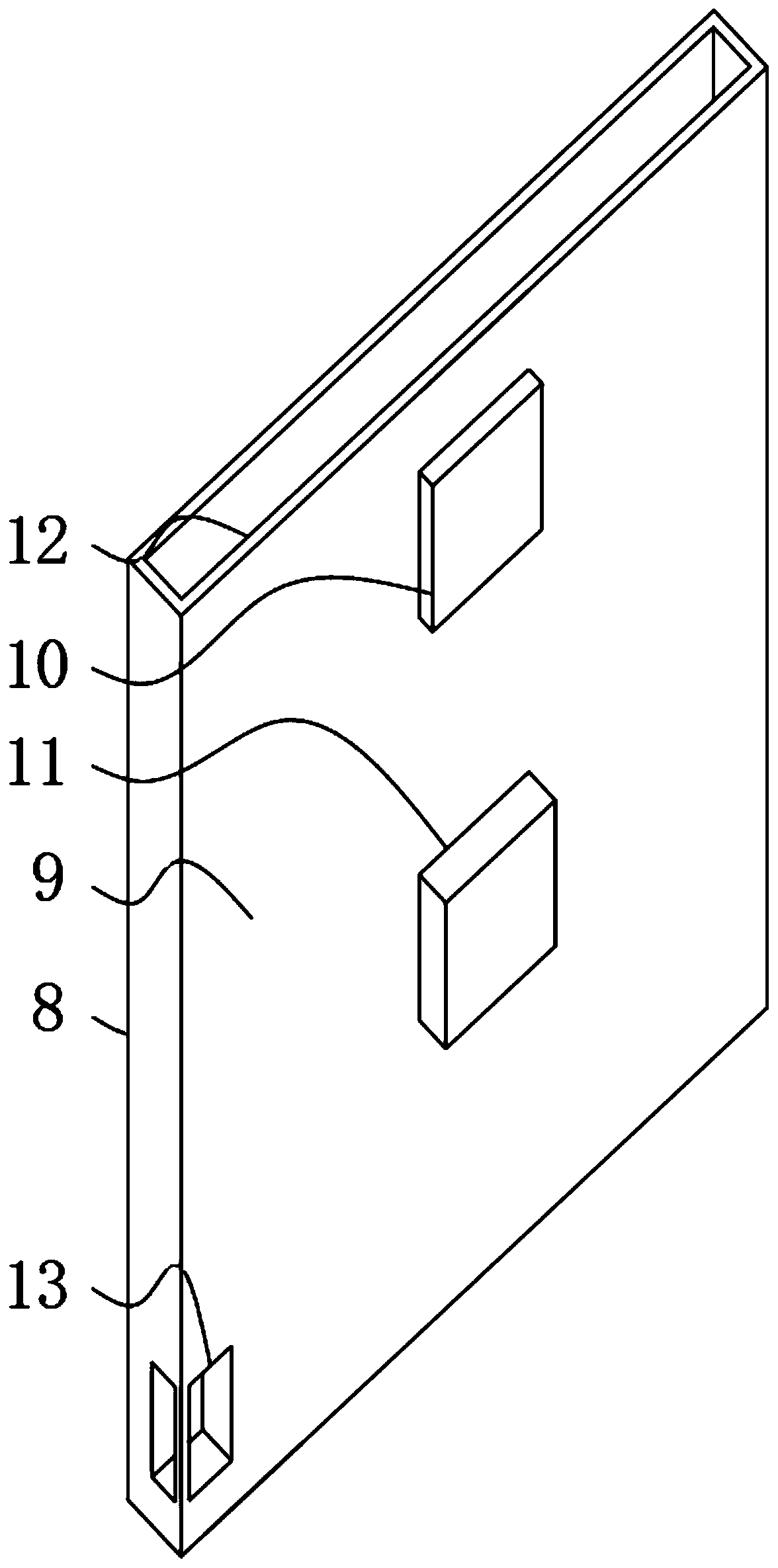

Image

  • Cutting wheel structure for ultrathin product
  • Cutting wheel structure for ultrathin product
  • Cutting wheel structure for ultrathin product

Examples


Embodiment Construction

[0026] The following will clearly and completely describe the technical solutions in the embodiments of the present invention with reference to the accompanying drawings in the embodiments of the present invention. Obviously, the described embodiments are only some, not all, embodiments of the present invention.

[0027] In the description of the present invention, unless otherwise stated, the meaning of "plurality" is two or more; the terms "upper", "lower", "left", "right", "inner", "outer" , "front end", "rear end", "head", "tail", etc. indicate the orientation or positional relationship based on the orientation or positional relationship shown in the drawings, and are only for the convenience of describing the present invention and simplifying the description, rather than Nothing indicating or implying that a referenced device or element must have a particular orientation, be constructed, and operate in a particular orientation should therefore not be construed as limiting ...


PUM


Abstract

The invention relates to a cutting wheel structure for an ultrathin product. The cutting wheel structure comprises a base disc and a side sewing mechanism, wherein tops of left and right ends of the base disc are equipped with transfer mechanisms; the side sewing mechanism is mounted at the top end of the base disc; the upper end of the side sewing mechanism is equipped with an upper disc; the bottom end of the middle part of the upper disc is fixedly provided with a centralizing mechanism; the outer side of the centralizing mechanism is equipped with an exchange base; the side end of the exchange base is equipped with a counter-through strip; and the end part of the counter-through strip is equipped with a mounting disc. The cutting wheel structure for the ultrathin product has the beneficial effects that: the exchange base can be conveniently moved through an embedded path, so that the height position of a cutting part of the end part of the exchange base is changed very conveniently; moreover, a central column and a movable strip are matched to move, so that the height position of the center column can be convenient changed to link the upper disc to synchronously move, and therefore, better control effect is achieved; and moreover, a sewing strip can be conveniently dismounted, so that the inner end of the device body is deformed and assembled.

Description

technical field [0001] The invention relates to the technical field of cutting, in particular to a cutter wheel structure for cutting ultra-thin products. Background technique [0002] Cutting is a physical action. Cutting in a narrow sense refers to cutting objects (such as food, wood and other objects with low hardness) with sharp tools such as knives; cutting in a broad sense refers to using tools, such as machine tools, flames, etc. to make objects down to disconnect. There is also a "cutting line" extended in mathematics, which refers to a straight line that can divide a plane into several parts. Cutting plays an important role in people's production and life, and some ultra-thin products generally use cutting devices when they are used. [0003] Due to the insufficient compact structure of the existing cutting device, its main body is too large, takes up a large space, is not practical enough, and is not convenient for storage, and the structures cannot cooperate wi...

Claims


Application Information

Patent Timeline
Patent Type & Authority Applications(China)
IPC IPC(8): B26D1/15B23D35/00B27C5/02B27C5/06
CPCB23D35/001B26D1/15B27C5/02B27C5/06
Inventor 张坤
Owner 深圳市新世纪拓佳光电技术有限公司
Why Eureka
Eureka Blog
Learn More