Valve plate assembly and valve core capable of precisely regulating temperature

A valve plate, precise technology, applied in the direction of sliding valve, multi-way valve, valve device, etc., can solve the problems of poor reducibility of the valve core, small rotation angle of the moving valve plate, inconvenient adjustment, etc., to achieve precise control and lower temperature rise Effect

Pending Publication Date: 2020-06-16
SHANGHAI YJ CARTRIDGE
View PDF0 Cites 0 Cited by
  • Summary
  • Abstract
  • Description
  • Claims
  • Application Information

AI Technical Summary

Problems solved by technology

[0003] The following problems exist in the existing temperature-regulating valve core: 1. In the main temperature-regulating range, the corresponding rotation angle of the moving valve plate is small; 2. The valve core has poor reducibility, making it difficult to accurately adjust the outlet water temperature
[0007] like figure 1 As shown, the existing spool is in the main temperature adjustment range, and there is a large difference between the forward rotation and reverse rotation of the movable valve plate. If the user wants to adjust the outlet water temperature to a certain temperature, he needs to repeatedly rotate forward and reverse. Moving valve plate, difficult to adjust, inconvenient to adjust

Method used


Image

  • Valve plate assembly and valve core capable of precisely regulating temperature
  • Valve plate assembly and valve core capable of precisely regulating temperature
  • Valve plate assembly and valve core capable of precisely regulating temperature

Examples


Embodiment 1

[0053] Embodiment 1, a valve assembly with precise temperature adjustment

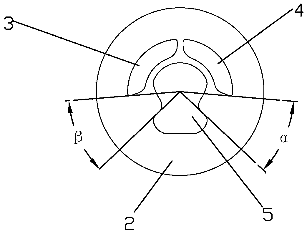
[0054] Such as Figure 3~5 As shown, a valve assembly that can be precisely adjusted in temperature includes a moving valve piece 1 and a fixed valve piece 2. The lower surface of the moving valve piece 1 is attached to the upper surface of the fixed valve piece 2, and relative rotation and movement can occur between the two. relatively sliding. The upper surface of the fixed valve sheet 2 is provided with a cold water inlet 3, a hot water inlet 4 and a mixed water outlet 5, wherein the mixed water outlet 5 is located in the middle of the fixed valve sheet 2, and the hot water inlet 4 is located at the bottom of the mixed water outlet 5. On the upper right side, the cold water inlet 3 is located on the upper left side of the mixed water outlet 5 . The left and right sides of the mixed water outlet 5 are arranged symmetrically. Such as Figure 5 As shown, the lower surface of the movable valve plate...

Embodiment 2

[0067] Embodiment 2, a valve core capable of precise temperature adjustment

[0068] Such as Figure 13 As shown, a valve core capable of precise temperature adjustment includes the valve plate assembly in Embodiment 1, and also includes a housing 6 , a base 7 , a control handle 8 , a rotating seat 10 and a chuck 9 . The swivel base 10 is rotatably installed on the upper end of the housing 6, and the control handle 8 is swingably installed in the swivel base 10. The control handle 8 and the swivel base 10 are connected by a rotating shaft 15 so that the control handle 8 two ends can swing. The chuck 9 , the movable valve plate 1 and the fixed valve plate 2 are installed in the housing 6 . The fixed valve plate 2 is fixed on the base 7, and the base 7 is provided with a block, which is snapped into the groove on the edge of the fixed valve plate 2, so that the fixed valve plate 2 and the base 7 are circumferentially fixed. A seal 16 is arranged between the fixed valve plate 2...


PUM


Abstract

The invention discloses a valve plate assembly and valve core capable of precisely regulating temperature. The valve plate assembly includes a moving valve plate and a fixed valve plate which are mutually fitted and rotated. The fixed valve plate is provided with a cold water inlet, a hot water inlet and a mixed water outlet. The mixed water outlet is located in the middle of the fixed valve plate. A main communicating groove is formed in the lower surface of the moving valve plate, and is located in the middle of the moving valve plate. The main communicating groove and the mixed water outletare communicated. The hot water inlet is located on the upper right side of the mixed water outlet, and the cold water inlet is located on the upper left side of the mixed water outlet; and a cold water supplementing groove and / or a hot water supplementing groove are further formed in the lower surface of the moving valve plate, the cold water supplementing groove is located on the lower right side of the main communicating groove, the cold water supplementing groove can simultaneously communicate the cold water inlet and the mixed water outlet, the hot water supplementing groove is located on the lower left side of the main communicating groove, and the hot water supplementing groove can simultaneously communicate the hot water inlet and the mixed water outlet. The valve plate assembly and valve core can precisely regulate the outlet water temperature within a main temperature regulating range.

Description

technical field [0001] The invention relates to a valve core, in particular to a valve plate assembly and a valve core capable of precise temperature regulation. Background technique [0002] At present, most spools use ceramic valve components to control the mixing ratio of cold and hot water when adjusting the outlet water temperature. As shown in the Chinese patent No. 2004201186654, a movable valve plate and a fixed valve plate are installed in the valve core, and the fixed valve plate is provided with a cold water inlet hole, a hot water inlet hole and a water outlet hole, and a communicating flow channel is opened on the movable valve plate. One end of the communication flow channel is always connected with the water outlet hole, and the other end of the communication flow channel can be connected with the cold water inlet hole and the hot water inlet hole simultaneously or separately by adjusting the position of the communication flow channel. The temperature of the ...

Claims


Application Information

Patent Timeline
Patent Type & Authority Applications(China)
IPC IPC(8): F16K11/078F16K3/314F16K3/34
CPCF16K3/314F16K3/34F16K11/0787
Inventor 陈绿林李传贺金阳水
Owner SHANGHAI YJ CARTRIDGE
Why Eureka
Try Eureka