
Method for inverting sea wave parameters by utilizing single shipborne X-band radar image

A radar image and X-band technology, applied in the direction of using re-radiation, radio wave reflection/re-radiation, radio wave measurement system, etc., can solve the problems of constantly changing position, inapplicable modulation transfer function, and difficulties in real-time observation of ocean waves

Active Publication Date: 2020-06-09
NANJING UNIV OF INFORMATION SCI & TECH
View PDF3 Cites 11 Cited by
  • Summary
  • Abstract
  • Description
  • Claims
  • Application Information

AI Technical Summary

Problems solved by technology

These methods all require a sequence of images observed by the radar over a period of time, usually a sequence of 32 or 64 images. When the signal-to-noise ratio of the radar is low, 512 images are required, which reduces the real-time performance of the observation data; In addition, the navigation of the ship will also cause the position of the observation area to change continuously, and the traditional modulation transfer function is not applicable, which brings great difficulties to the real-time observation of waves, and the real-time performance of observation parameters is very important for the safe navigation of the ship.
Therefore, inventing a simple and feasible method for inverting sea wave parameters using a single ship-borne X-band radar image to solve the problem in the prior art that only long-term X-band radar image sequences can be used to invert sea wave information Become an urgent technical problem to be solved in this technical field

Method used


Image

  • Method for inverting sea wave parameters by utilizing single shipborne X-band radar image
  • Method for inverting sea wave parameters by utilizing single shipborne X-band radar image
  • Method for inverting sea wave parameters by utilizing single shipborne X-band radar image

Examples


Embodiment Construction

[0038] Embodiments of the present invention will be further described in detail below in conjunction with the accompanying drawings.

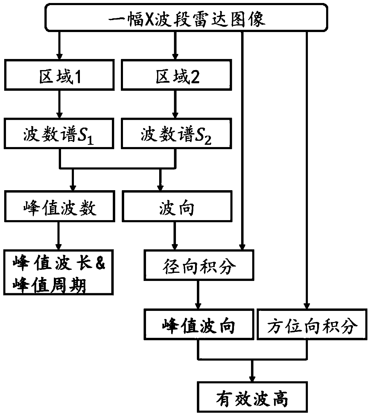
[0039] Such as figure 1 As shown, the present invention is a method for inverting sea wave parameters using a single ship-borne X-band radar image of the present invention and mainly includes three parts: the first part is to select images at different positions to obtain wave spectrum and peak parameters; the second part is to estimate the peak wave direction and remove the direction ambiguity; the third part is to estimate the effective wave height of the wave. The various details involved in the technical solution of the present invention will be described in detail below in conjunction with examples.

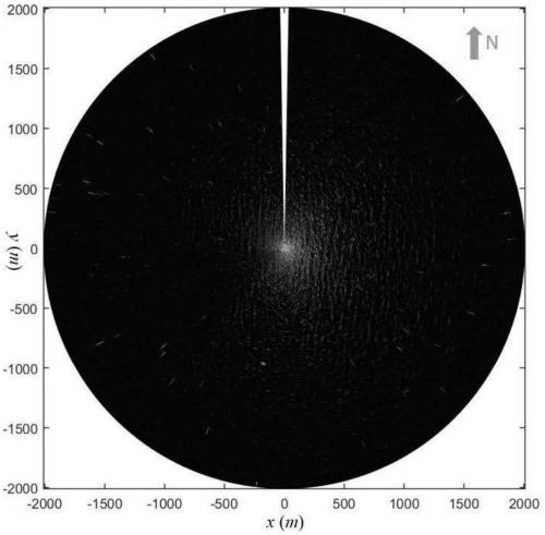
[0040] figure 2 is an image from a shipboard X-band radar observation with 0° pointing due north.

[0041] Step 1: Select the inversion area: for figure 2 The X-band radar grayscale image I(r, θ) is shown, where r is the distance from t...


PUM


Abstract

The invention discloses a method for inverting sea wave parameters by using a single shipborne X-band radar image, which comprises the following steps: selecting an inversion area, acquiring a grayscale image by using an X-band radar, and selecting an area 1 and an area 2 with the same distance and different azimuth angles; respectively interpolating the gray values of the radar images in the area1 and the area 2 into a rectangular coordinate system, performing Fourier transform to obtain a wave number spectrum of the area 1 and a wave number spectrum of the area 2, finding out peak values and corresponding wave number components of the wave number spectrums of the area 1 and the area 2, and solving peak value wave numbers and peak value wave directions of the area 1 and the area 2; solving a peak wave number and a peak wave direction according to the wave number spectrums of the area 1 and the area 2; judging and eliminating direction ambiguity of the peak wave direction; selecting the direction in the vicinity of the direction of the main wave, integrating the gray value, and solving related sea wave parameters. According to the method, the change of the sea wave parameters canbe obtained in real time by collecting the grayscale image in real time and extracting the related parameters for calculation and analysis.

Description

technical field [0001] The invention belongs to the technical field of marine remote sensing, and in particular relates to a method for retrieving sea wave parameters by using a single ship-borne X-band radar image. Background technique [0002] Ocean waves are one of the most common ocean phenomena, which have an important impact on the safe navigation of ships and the planning of routes. The commonly used wave observation method is wave buoy, but it can only obtain the wave changes at local points or lines, and generally needs to be anchored to a fixed position, and cannot be used for shipboard observation. Remote sensing technology is also used to observe ocean waves. The satellite wave spectrometer is a new type of ocean wave spectrum observation instrument, which has the advantages of a large observation range, but its products are immature and have low time and space resolution, which cannot meet business applications. Coherent and non-coherent X-band radars are widel...

Claims


Application Information

Patent Timeline
Patent Type & Authority Applications(China)
IPC IPC(8): G01S13/95G01S7/41
CPCG01S7/41G01S13/95Y02A90/10
Inventor 陈忠彪何宜军张宁宁温静涵范仲珏
Owner NANJING UNIV OF INFORMATION SCI & TECH
Learn More