Control method and device for lamp in household appliance

A technology of household appliances and control methods, applied in the direction of energy-saving control technology, electrical components, etc., which can solve the problems such as the inability to realize the state change of lights

Inactive Publication Date: 2020-06-05
WUXI FILIN ELECTRONICS CO LTD
View PDF18 Cites 0 Cited by
  • Summary
  • Abstract
  • Description
  • Claims
  • Application Information

AI Technical Summary

Problems solved by technology

[0005] For this reason, this application proposes a control method and device for lamps in household appliances, in order to realize the state that the target lamp should be in by acquiring the state that the target lamp should be in. The port corresponding to the lamp outputs the electrical signal of the unit duration, if the state that the target lamp needs to be in is the second state, then output the electrical signal of the unit duration to the port corresponding to the target lamp at intervals of the second duration, and then control the target lamp to light up, by Therefore, by modifying the software to control the lighting of the target lamp, the cost is saved, the modification method is flexible, and the user experience is improved, and it solves the problem of only relying on the existing hardware after the hardware circuit of the household appliance in the prior art has been determined. The technical problem that the circuit cannot realize the state change of the lamp

Method used


Image

  • Control method and device for lamp in household appliance
  • Control method and device for lamp in household appliance
  • Control method and device for lamp in household appliance

Examples


Embodiment Construction

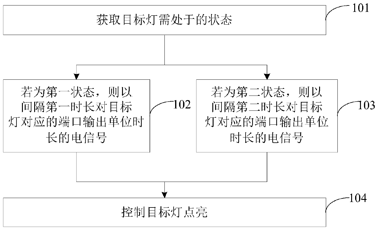
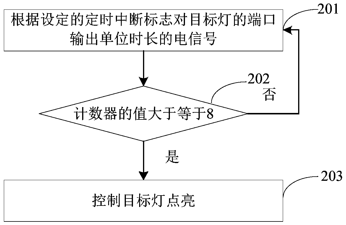
[0026] Embodiments of the present application are described in detail below, examples of which are shown in the drawings, wherein the same or similar reference numerals denote the same or similar elements or elements having the same or similar functions throughout. The embodiments described below by referring to the figures are exemplary, and are intended to explain the present application, and should not be construed as limiting the present application.

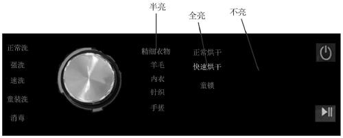
[0027] In the prior art, the full-brightness and half-brightness function of the lamp in the household appliance is realized by modifying the hardware circuit of the household appliance, but when the household appliance leaves the factory, the hardware circuit has been determined and cannot be changed. Therefore, it is no longer possible to realize the full-brightness and half-brightness function of the lamp in the household appliance by modifying the hardware circuit.

[0028] In view of the above-mentioned prior art, the e...


PUM


Abstract

The invention provides a control method and device for a lamp in a household appliance. The method comprises the steps of obtaining a state in which a target lamp needs to be, and if the state that the target lamp needs to be in is a first state, outputting an electric signal per unit time length to the port corresponding to the target lamp at an interval of a first time length, and if the state that the target lamp needs to be in is a second state, outputting an electric signal per unit time length to the port corresponding to the target lamp at an interval of a second time length, thereby controlling the target lamp to be turned on. Through the method, by judging the acquired state of a target lamp of the household appliance, the electric signal of the unit time length is output to the port corresponding to the target lamp at the corresponding interval time length, so that the target lamp of the household appliance is turned on, and the technical problem that the state change of thelamp cannot be realized by only depending on the existing hardware circuit after the hardware circuit of the household appliance is determined in the prior art is solved.

Description

technical field [0001] The present application relates to the technical field of home appliances, in particular to a method and device for controlling lights in a home appliance. Background technique [0002] With the continuous development of science and technology, people's pursuit of material life is also constantly improving. Therefore, in order to meet people's living needs, household appliances have more and more functions. The user can determine the available functions of the household appliance by observing the display state of the function option light of the household appliance. [0003] In the prior art, the display state of the lamp is mostly realized by modifying the hardware circuit of the household appliance. However, in the actual use process, since the hardware circuit of the household appliance has been determined during production, it is impossible to adjust the display state of the lamp. Modifications have seriously affected the user experience. Conten...

Claims


Application Information

Patent Timeline
IPC IPC(8): H05B47/10
CPCY02B20/40
Inventor 玄柳查世尧
Owner WUXI FILIN ELECTRONICS CO LTD
Why Eureka
Try Eureka