


Quick Research
Generate reliable direction feasibility study reports for your R&D in just a few steps.

Technical Q&A
Discover and master advanced knowledge NOW. Basics, ideas, possibilities, all at once.

Find Solutions
As an expert in R&D theories, this can generate solutions to your technical problems instantly.

Evaluate Feasibility
Analyze your overall solution with one click, know your potential R&D risks in advance.

Monitor Landscape
Get weekly tech updates, stay abreast of the latest tech innovations and key insights.
Shearing type slurry pulse generation device
A technology of mud pulse and generating device, which is used in surveying, wellbore/well components, earth-moving drilling, etc., can solve the problems of poor sealing effect due to the difference in the state of piston components, large inertia of rotor drive shaft motion, and easy failure of sealing components, etc. Achieve the effect of simple and reliable structure, increase service life and reliability, and reduce the risk of mud invasion
- Summary
- Abstract
- Description
- Claims
- Application Information
AI Technical Summary
Problems solved by technology
Method used
Image

Examples
Embodiment 1
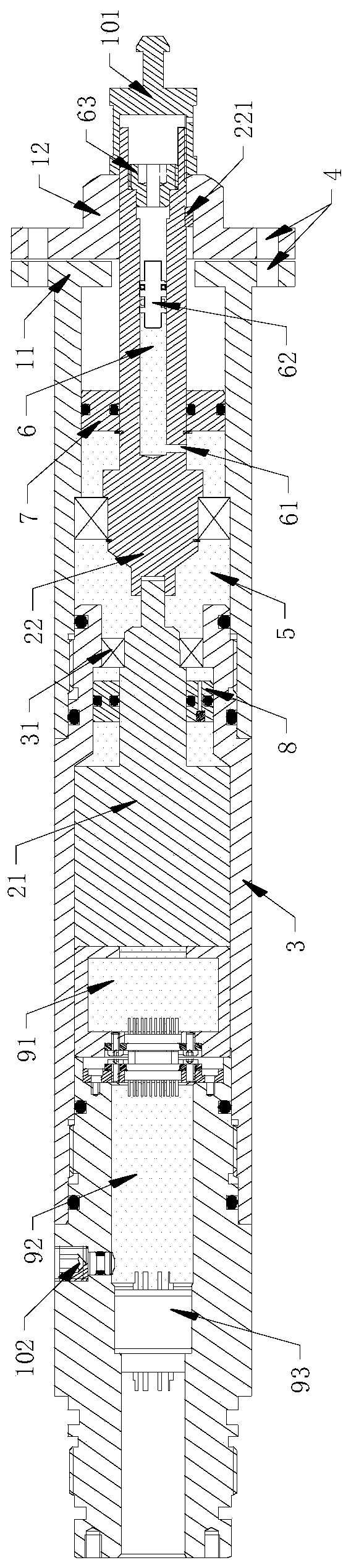
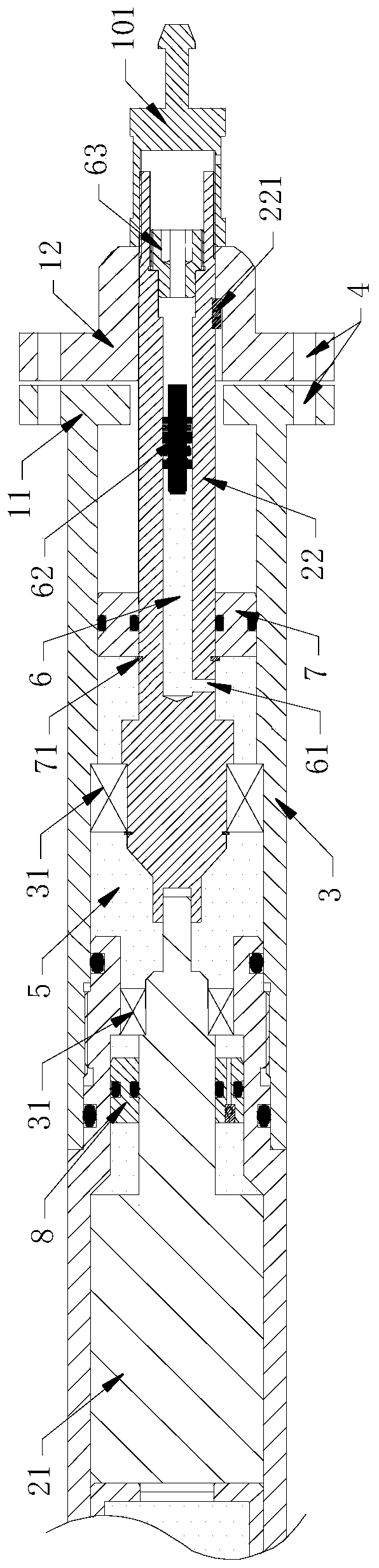
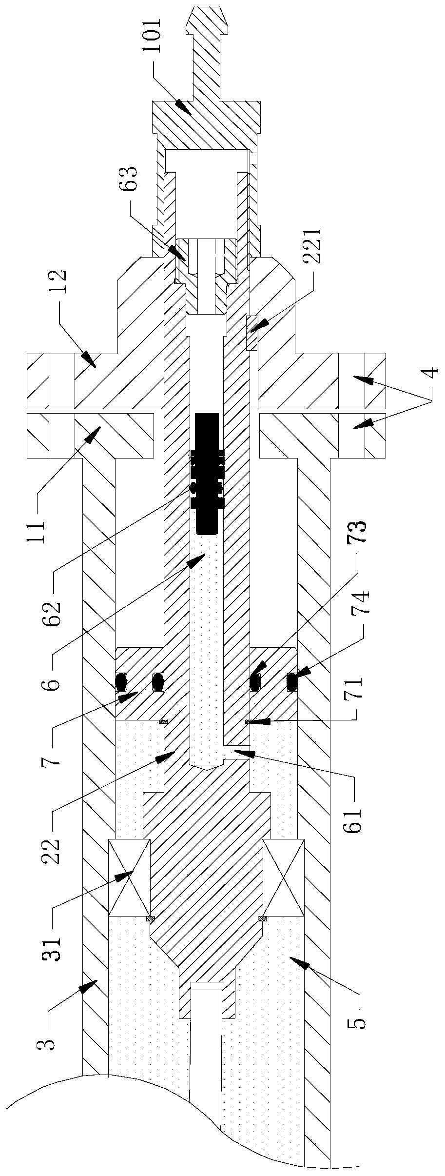
[0037] A shear type mud pulse generating device, such as Figure 1-Figure 3 As shown, it includes a pulse generating part 1, a driving part 2 and a housing 3, wherein the pulse generating part 1 includes a stator 11 and a rotor 12 arranged in cooperation, and mud flow holes 4 are arranged on the stator 11 and the rotor 12; The part 2 includes a motor 21 and a rotor driving part 22, one end of the rotor driving part 22 is connected to the motor 21, and the other end of the rotor driving part 22 is connected to the rotor 12; the casing 3 is arranged on the periphery of the driving part 2, and the driving part 2 is connected to the shell Between the inner walls of the body 3 is an oil immersion space 5; the rotor driving member 22 is provided with a hollow part 6, one end of the hollow part 6 communicates with the outside world, the other end of the hollow part 6 is a blind hole, and the side wall of the hollow part 6 is provided with an immersion hole. The oil space 5 communicat...
Embodiment 2
[0052] This embodiment also includes a second balance plunger 7 on the basis of Embodiment 1, such as Figure 1-Figure 3 As shown, the second balance plunger 7 is arranged between the rotor driving member 22 and the housing 3 , and the second balance plunger 7 is arranged between the oil hole 61 and the rotor 12 in the axial direction.
[0053] In the actual work of the second balance plunger 7, under normal conditions, the second balance plunger 7 is mainly used to prevent mud from entering from the space between the rotor drive member 22 and the housing 3, and the second balance plunger 7 mainly rotates The dynamic sealing function is the main function, on the other hand; the second balance plunger 7 and the first balance plunger 62 in Embodiment 1 can also cooperate with each other to do reciprocating motion; when the external mud pressure is large, the first balance piston moves toward the motor 21 direction movement is used for pressure compensation, but when the external...
Embodiment 3
[0058] On the basis of Embodiment 1, a third balance plunger 8 is also included, such as Figure 1-Figure 3 As shown, the third balance plunger 8 is arranged between the shaft of the motor 21 and the housing 3, as Figure 5 As shown, the third balance plunger 8 includes a third plunger body 81, and the third plunger body 81 is provided with an oil passage 811 and a one-way valve 812, and one end of the one-way valve 812 communicates with the oil passage 811, and the one-way The other end of the valve 812 is in communication with the oil immersion space 5, the end of the third plunger body 81 close to the shaft of the motor 21 is provided with a third seal 813, and the end of the third plunger body 81 close to the inner wall of the housing 3 is provided with a fourth Seal 814 .
[0059]When working, the third balance plunger 8 is used to protect the motor 21 and put mud into the motor 21. A one-way valve 812 is set in the third balance plunger 8 so that the liquid can only flo...
PUM
 Abstract
Description
Claims
Application Information
 - R&D Engineer
- R&D Manager
- IP Professional
- Industry Leading Data Capabilities
- Powerful AI technology
- Patent DNA Extraction
Browse by: Latest US Patents, China's latest patents, Technical Efficacy Thesaurus, Application Domain, Technology Topic, Popular Technical Reports.
© 2024 PatSnap. All rights reserved.Legal|Privacy policy|Modern Slavery Act Transparency Statement|Sitemap|About US| Contact US: help@patsnap.com