Forming tooling for a laminated unit body of a composite fan blade

A technology for forming tooling and fan blades, which is applied in the field of composite material manufacturing, can solve the problems of complex forming process, long layup cycle, and high requirements on the surface accuracy of parts with thickness changes from tenon to blade tip, so as to improve production efficiency and improve the surface. Quality, the effect of shortening the operation time

Active Publication Date: 2021-12-03
AVIC COMPOSITES
View PDF0 Cites 0 Cited by
  • Summary
  • Abstract
  • Description
  • Claims
  • Application Information

AI Technical Summary

Problems solved by technology

With the continuous development of high thrust-to-weight ratio engines, the development of fan blades is also deepening. The fan blades have developed from early metal materials to today's carbon fiber resin-based composite materials. Due to the large torsion and double curvature of the composite fan blades themselves The characteristics of profile, mortise and blade tip thickness change drastically, and the precision of part profile is high, which makes the forming process itself very complicated.
Especially for the tenon part of the blade, since the position of the tenon is the key position where the blade is connected to the blisk, it bears the largest load, resulting in a complex layer configuration in this area, and there are many layer units. The layer unit is composed of The composition unit of the blade layup is used for filling between the blade tenons. Layers are stacked on the blade forming tooling in sequence. This stacking method has disadvantages such as long stacking cycle and low stacking efficiency, which will lead to higher production costs in the production process of composite fan blades.

Method used


Image

  • Forming tooling for a laminated unit body of a composite fan blade
  • Forming tooling for a laminated unit body of a composite fan blade
  • Forming tooling for a laminated unit body of a composite fan blade

Examples


Embodiment Construction

[0023] The technical scheme of the present invention will be described in further detail below in conjunction with accompanying drawing and embodiment:

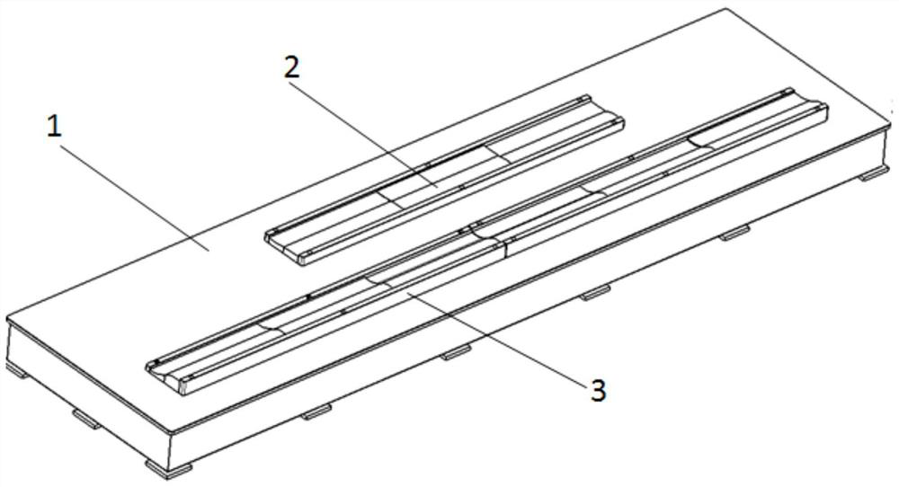
[0024] See attached figure 1 , 2 As shown, the molding tooling of this kind of composite fan blade layup unit includes a layup platform 1 and a layup working surface 2 arranged on the layup platform 1, and layup datums are set on both sides of the layup working surface 2 Block 3 is used as a lay-up reference, and the number of lay-up working surfaces 2 is the same as the number of lay-up units in the tenon of the composite fan blade.

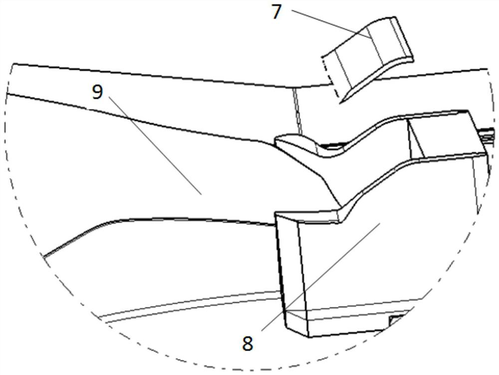
[0025] In this embodiment, the shape of the lay-up working surface 2 is center-symmetrical, and the two sides of the center point are the concave working surface 4 and the convex working surface 5 respectively, and the concave working surface 4 is used for the suction of the tenon of the composite fan blade. The suction surface layer unit body 6 on the surface side, the convex working surface...


PUM


Abstract

The invention relates to a forming tool for a composite fan blade laminate unit body, the forming tool includes a laying platform (1) and a laying working surface (2) arranged on the laying platform (1), during the laying work Both sides of the surface (2) are provided with lay-up reference blocks (3) as lay-up references, and the number of lay-up working faces (2) is the same as the number of lay-up units in the tenons of composite fan blades. Adopting the tooling described in the present invention can use the ply unit body to form in batches in advance, and at the same time, when laying up the ply unit body, the symmetrical concave surface and convex surface unit body can be formed on the same molding die surface at one time, which improves the profile of the unit body quality. The pre-formed ply units are then placed on the blade forming tooling as integral laminate blocks during the composite fan blade layup process. Under the premise of ensuring the accuracy of the surface of the ply unit, the operation time of blade ply laying can be greatly shortened, and the production efficiency of the blade can be improved.

Description

technical field [0001] The invention relates to a molding tool for a composite material fan blade lamination unit, which belongs to the technical field of composite material manufacturing. Background technique [0002] The fan blade is one of the most representative and important parts of the high thrust-to-weight ratio turbofan engine, and the performance of the turbofan engine is closely related to its development. With the continuous development of high thrust-to-weight ratio engines, the development of fan blades is also deepening. The fan blades have developed from early metal materials to today's carbon fiber resin-based composite materials. Due to the large torsion and double curvature of the composite fan blades themselves The profile, tenon to blade tip thickness changes drastically, and the precision of the part profile is high, making the forming process itself very complicated. Especially for the tenon part of the blade, since the position of the tenon is the ke...

Claims


Application Information

Patent Timeline
Patent Type & Authority Patents(China)
IPC IPC(8): B29C70/34B29C70/54B29L31/08
CPCB29C70/342B29C70/54B29L2031/082
Inventor 苏震宇邱启艳蒋金龙
Owner AVIC COMPOSITES
Why Eureka
Try Eureka