Waist massage device for orthopedics department

A waist and orthopedics technology, applied in the field of waist massage devices for orthopedics, can solve problems such as unsatisfactory massage effect and inability to apply heat on the waist, and achieve excellent overall effect and excellent massage effect

Inactive Publication Date: 2020-05-29
唐英丽
View PDF1 Cites 1 Cited by
  • Summary
  • Abstract
  • Description
  • Claims
  • Application Information

AI Technical Summary

Problems solved by technology

[0004] The present invention aims at the problem that the existing waist massage rehabilitation device has unsatisfactory massage effect and cannot perform hot compresses on the waist, so an orthopedic waist massage device with ideal massage effect and hot compress effect is invented

Method used


Image

  • Waist massage device for orthopedics department
  • Waist massage device for orthopedics department
  • Waist massage device for orthopedics department

Examples


Embodiment 1

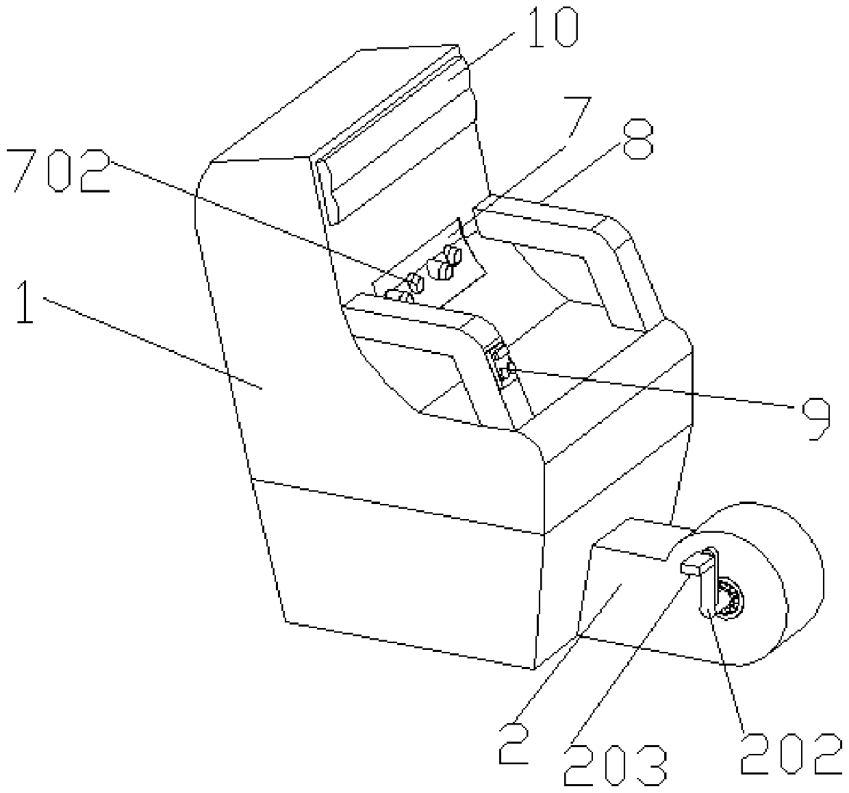
[0030] Embodiment 1 has introduced a kind of orthopedics waist massage device, and main structure comprises seat main body 1 and pedal drive box 2, wherein the included angle between seat and its backrest in seat main body 1 is 120 °, and this angle is The optimal angle for the patient to lie on the seat main body 1, and a sponge headrest 10 is also provided at the upper end of the front side of the seat main body 1 for comfort considerations. Pedal drive box 2 is arranged on the front side lower end of seat main body 1, and the front end of pedal drive box 2 is provided with large gear 201 inside, and the both sides of large gear 201 are all connected with pedal rod 202, two pedal rods The ends of 202 all stretch out the outside of pedal drive box 2 and are connected with pedal 203, the patient lies on the seat main body 1 and can drive big gear 201 to rotate by leg exerting force.

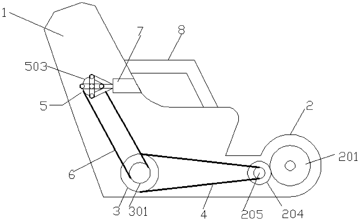
[0031] A pinion 204 is arranged on the lower left side of the bull gear 201, and the pinion 2...

Embodiment 2

[0035] Embodiment 2 increases the hot compress effect on the basis of Embodiment 1, and it is specifically introduced below:

[0036] Embodiment 2 introduces a waist massage device for orthopedics with its own hot compress effect. The main structure includes a seat body 1 and a pedal driving box 2. The pedal driving box 2 is arranged at the lower end of the front side of the seat body 1. The pedals The inside of the front end of the driving box 2 is provided with a large gear 201, the two sides of the large gear 201 are connected with pedal rods 202, and the ends of the two pedal rods 202 stretch out from the outside of the pedal driving box 2 and are connected with feet. Pedal 203, the patient lies on the seat main body 1 and can drive the large gear 201 to rotate through leg force.

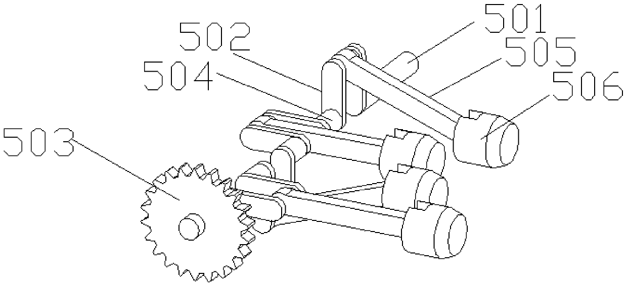
[0037] A pinion 204 is arranged on the lower left side of the bull gear 201, and the pinion 204 meshes with the bull gear 201. An intermediate pulley 3 is arranged at the inner lower end of the ...


PUM


Abstract

The invention belongs to the technical field of medical instruments for the orthopedics department and particularly relates to a waist massage device for the orthopedics department. The device comprises a chair body and a pedal driving box, wherein the pedal driving box is arranged at the lower end of the front side surface of the chair body, a large gear is arranged in the front end of the pedaldriving box, two side surfaces of the large gear are connected with pedal levers, end parts of the two pedal levers extend out of the pedal driving box and are connected with pedals, and a small gearis arranged on the lower left of the large gear. A connection shaft of a massage pushing mechanism is driven to rotate by the gears, pulleys, a triangular belt and a chain, pushing pistons on different U-type connecting frames sequentially move back and forth in round through cavities of a massage top seat under the action of the U-type connecting frames arranged at staggered angles in space, massage heads in different round through cavities are pushed out intermittently in an intermittent staggered manner under the action of push rods, so that the waist of a patient is massaged, and parts forwaist massage are very comprehensive and have excellent massage effect.

Description

technical field [0001] The invention belongs to the technical field of orthopedic medical devices, in particular to a waist massage device for orthopedics. Background technique [0002] In clinical medicine, orthopedic surgery and postoperative rehabilitation are complementary, and formal rehabilitation is a necessary means to help achieve the purpose of surgery and ensure the success of surgery. In the waist rehabilitation of orthopedic patients, it is necessary to massage the waist to speed up the recovery effect, while the general orthopedic patients use medical staff to massage the waist, which not only has poor massage effect, but also greatly increases the workload of medical staff . Though existing part is used for the device of waist massage on the market, it all has deficiency. [0003] For example, the patent No. CN106389088B discloses a waist massage rehabilitation device, which includes a base, a bed board assembly, an equipment assembly, a backrest assembly an...

Claims


Application Information

Patent Timeline
Patent Type & Authority Applications(China)
IPC IPC(8): A61H23/00
CPCA61H23/006A61H2201/0149A61H2201/0207A61H2201/1261A61H2205/08
Inventor 唐英丽
Owner 唐英丽
Why Eureka
Try Eureka