A portable measuring device with adjustable depth for rock and soil geological survey
A technology of geological survey and measurement device, which is applied in the field of basic soil survey, sampling device, construction, etc., can solve the problems such as the inability to bring geotechnical samples of different depths back to indoor testing, the inconvenience of mechanical transportation on the construction site, and the inconvenience of drilling work, etc. To achieve the effect of simple structure, increased convenience, and increased convenience of adjustment
- Summary
- Abstract
- Description
- Claims
- Application Information
AI Technical Summary
Problems solved by technology
Method used
Image
Examples
Embodiment 1
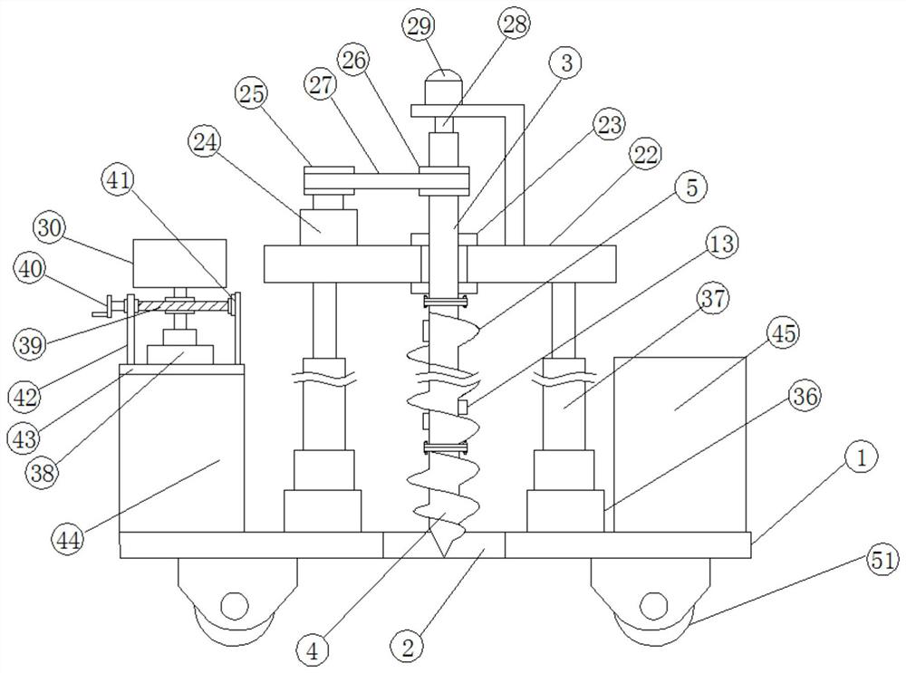
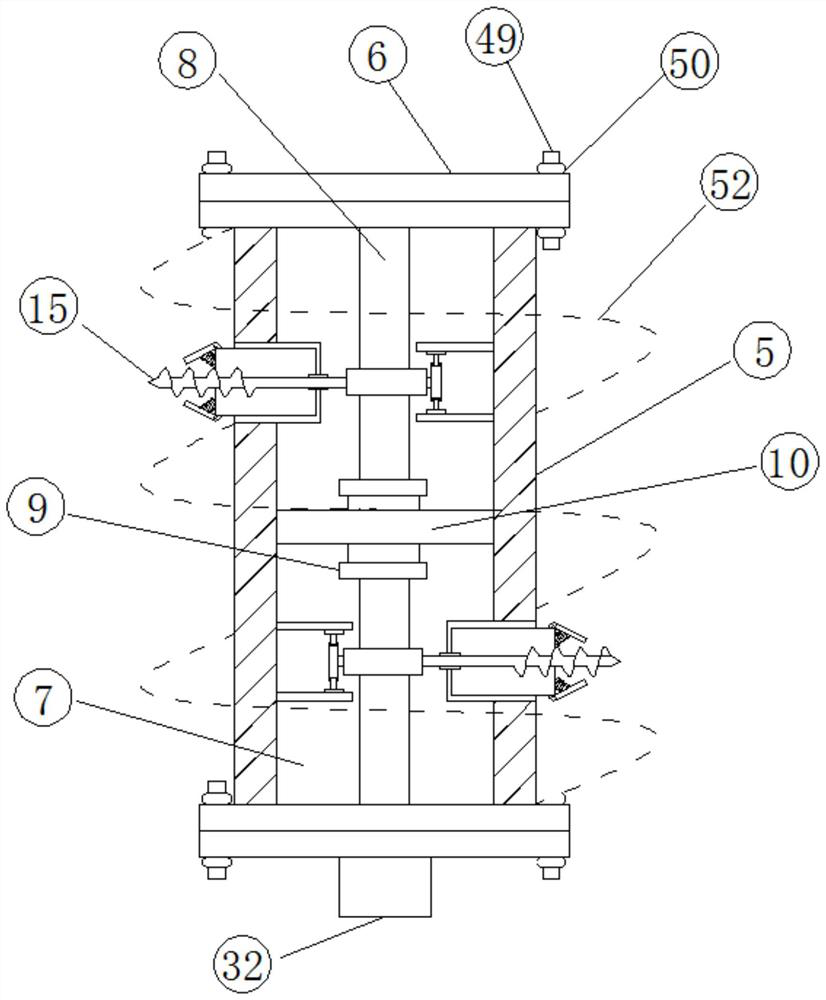
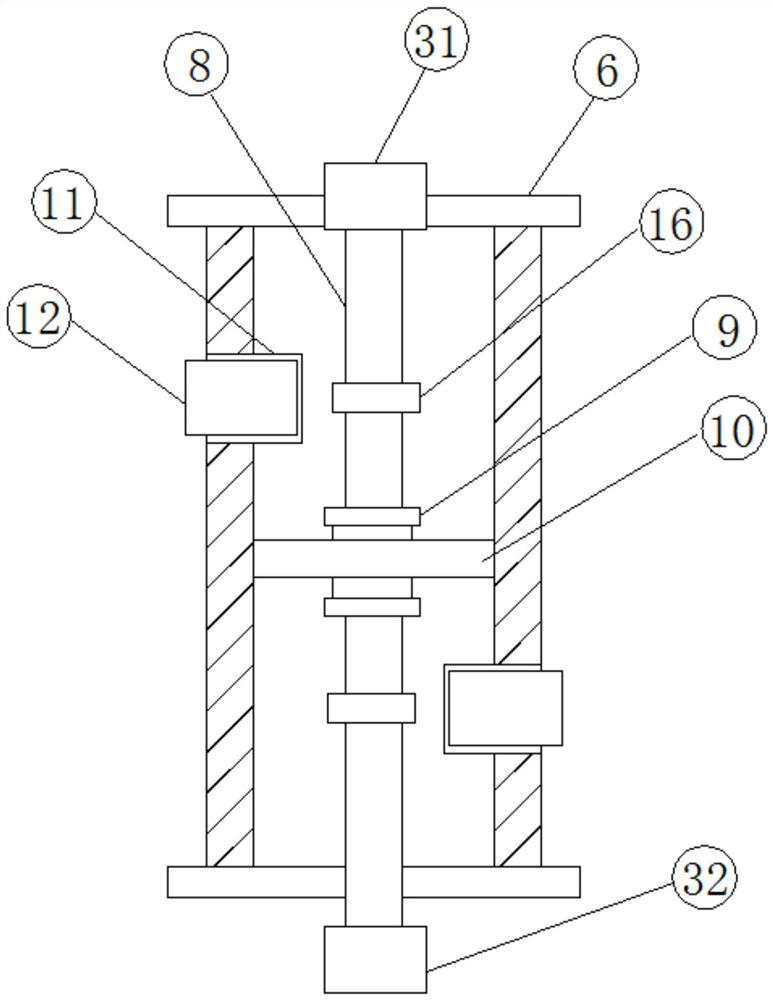
[0031] see Figure 1-5According to an embodiment of the present invention, a portable measuring device with adjustable depth for rock and soil geological survey includes a base plate 1, a through hole 2 is arranged in the middle of the base plate 1, and a drilling sampling device is arranged above the through hole 2 , the borehole sampling device includes a first rotating shaft 3, a drill bit 4 is arranged below the first rotating shaft 3, and several connecting drill rods 5 are arranged between the drill bit 4 and the first rotating shaft 3, and the connecting Both ends of the drill rod 5 are provided with a first flange 6, and the connecting drill rod 5 is respectively connected with the drill bit 4 and the first rotating shaft 3 through a second flange, and the connecting drill rod 5 is provided with There is a first helical blade 52, a cavity 7 is provided inside the connecting drill pipe 5, a rotating shaft 8 is provided inside the cavity 7, and a first bearing sleeve 9 i...
Embodiment 2
[0033] see figure 2 , 3 , 4. For the connection device, the connection device includes a first fixed block 31 and a second fixed block 32, and the first fixed block 31 is fixed to one end of the second rotating shaft 28 and the rotating shaft 8, The second fixed block 32 is fixed to the other end of the rotating shaft 8 away from the first fixed block 31, and a plurality of clamping blocks 33 are fixed on the edge of the first fixed block 31, and the second fixed block One side of 32 is provided with a limiting groove 34, and the limiting groove 34 is matched with the first fixing block 31, and the edge of the limiting groove 34 is located on the second fixing block 32 and is provided with a card slot 35 , the clamping block 33 is matched with the clamping groove 35, and the connecting device can realize that when the connecting drill rods 5 are connected, the two rotating shafts 8 inside the connecting drill rods 5 can be engaged and connected, and at the same time, it is c...
Embodiment 3
[0035] see figure 1 , for the rotating device, the rotating device includes a rotating base 38, one side of the rotating base 38 is fixedly provided with a rotating rod, and the end of the rotating rod away from the rotating base 38 is fixedly connected with the theodolite 30, The second worm gear is fixedly arranged on the rotating rod, and one side of the second worm gear meshes with the second worm 39, and one end of the second worm 39 is fixedly provided with a rotating handle 40, and the second worm 39 is away from One end of described rotary handle 40 is provided with bearing seat, and described bearing seat is fixedly connected with support frame 41, and one side of described rotary handle 40 is positioned at described second worm screw 39 and is provided with support rod 42, and rotating device is convenient for theodolite 30 adjusts the magnetic field, which increases the convenience of adjustment, and at the same time, the support frame 41 and the support rod 42 can ...
PUM
 Abstract
Description
Claims
Application Information
 - R&D
- Intellectual Property
- Life Sciences
- Materials
- Tech Scout
- Unparalleled Data Quality
- Higher Quality Content
- 60% Fewer Hallucinations
Browse by: Latest US Patents, China's latest patents, Technical Efficacy Thesaurus, Application Domain, Technology Topic, Popular Technical Reports.
© 2025 PatSnap. All rights reserved.Legal|Privacy policy|Modern Slavery Act Transparency Statement|Sitemap|About US| Contact US: help@patsnap.com


