Real-time monitoring system and method for roadway surrounding rock

A real-time monitoring system and surrounding rock technology, applied in the direction of measuring devices, measuring ultrasonic/sonic/infrasonic waves, instruments, etc., can solve the problems of insufficient accuracy of measurement data, difficulty in accurately obtaining floor drum volume, large errors, etc.

Active Publication Date: 2021-06-29
TIANDI SCI & TECH CO LTD
View PDF0 Cites 0 Cited by
  • Summary
  • Abstract
  • Description
  • Claims
  • Application Information

AI Technical Summary

Problems solved by technology

However, there are three obvious defects in the application of this displacement monitoring method: 1. The interval time is too long, resulting in insufficient data continuity, especially in the impact mine pressure roadway, which cannot reflect the displacement caused by unpredictable vibration in time
2. During the application process of the roadway (especially the recovery roadway), the flow of people and goods on the bottom plate is huge, and the markings are easily obliterated, which greatly increases the difficulty of monitoring, especially the real bottom drum volume of the bottom plate is difficult to obtain accurately
3. It is easy to cause errors when measuring with a tape measure. The cumulative error of the measurement error of each data is larger, resulting in the obvious lack of accuracy of the measurement data.
[0004] In addition, the existing roadway surrounding rock vibration monitoring is often not at the same measuring point as the roadway surrounding rock displacement monitoring
That is to say, there is a certain distance between the displacement monitoring point of the surrounding rock in the roadway and the vibration monitoring point of the surrounding rock in the roadway. The real impact of displacement

Method used


Image

  • Real-time monitoring system and method for roadway surrounding rock
  • Real-time monitoring system and method for roadway surrounding rock
  • Real-time monitoring system and method for roadway surrounding rock

Examples


Embodiment Construction

[0036] In order to make the purpose, technical solutions and advantages of the embodiments of the present invention clearer, the technical solutions in the embodiments of the present invention will be clearly and completely described below in conjunction with the drawings in the embodiments of the present invention. Obviously, the described embodiments It is a part of embodiments of the present invention, but not all embodiments. Based on the embodiments of the present invention, all other embodiments obtained by persons of ordinary skill in the art without making creative efforts belong to the protection scope of the present invention.

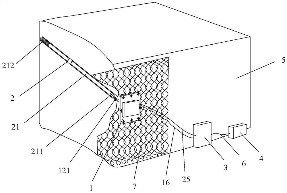
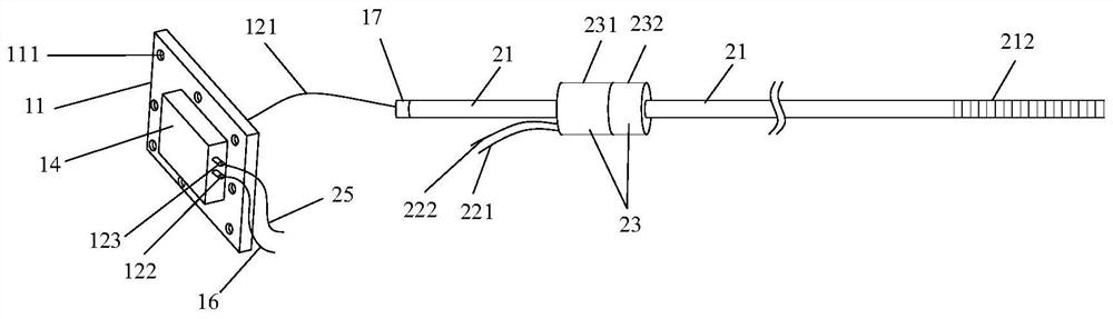
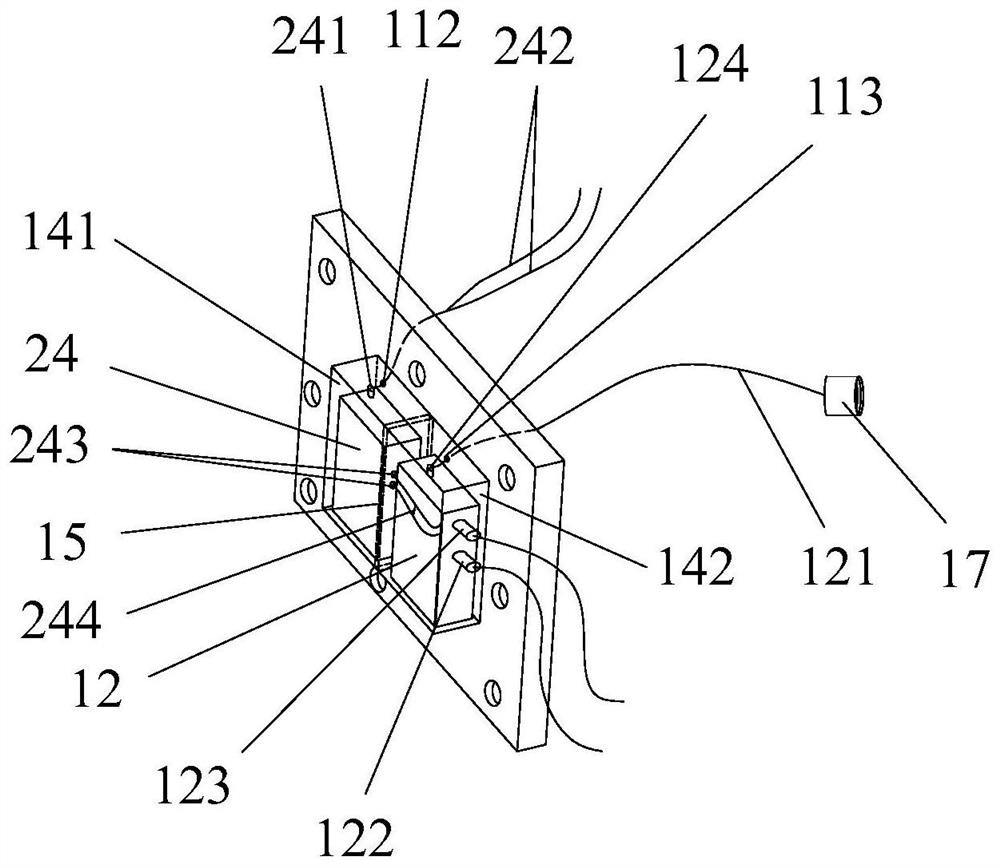
[0037] like Figure 1 to Figure 5 As shown, the embodiment of the present invention provides a real-time monitoring system for roadway surrounding rock, including a surrounding rock displacement monitoring mechanism 1 and a surrounding rock vibration monitoring mechanism 2 .

[0038] Surrounding rock displacement monitoring mechanism 1 include...


PUM


Abstract

The invention relates to the technical field of roadway surrounding rock monitoring, in particular to a real-time monitoring system and method for roadway surrounding rock. The system includes a surrounding rock displacement monitoring mechanism and a surrounding rock vibration monitoring mechanism. The surrounding rock displacement monitoring mechanism includes a fixed chassis and a cable-type displacement sensor. The cable-type displacement sensor is installed on the fixed chassis. The surrounding rock vibration monitoring mechanism includes an anchor rod and a vibration sensor. , the vibration sensor is installed on the anchor rod, and the stay wire of the pull-wire displacement sensor is connected with the anchor rod. The system and method for real-time monitoring of roadway surrounding rock provided by the present invention can accurately reflect the displacement change and vibration change of the same measuring point of roadway surrounding rock, and the obtained monitoring data has the advantages of real-time continuity, high precision and high reliability. Therefore, it has positive guiding significance for the analysis of the deformation and failure mechanism of the rock burst roadway surrounding rock.

Description

technical field [0001] The invention relates to the technical field of roadway surrounding rock monitoring, in particular to a real-time monitoring system and method for roadway surrounding rock. Background technique [0002] Mine roadway (especially mining roadway) is an underground passage to ensure the safe and efficient mining of coal mines, and the stability of its surrounding rock is closely related to the safe and efficient mining of coal mines. For a long time, the monitoring and data acquisition of the displacement and vibration of the surrounding rock of the roadway has been a strong support for the analysis of the deformation and failure of the surrounding rock of the roadway. [0003] At present, the commonly used displacement monitoring method of roadway surrounding rock is the arrangement of cross measuring points. The method is to arrange a total of four measuring points in the middle of the roof and floor of the roadway and the middle of the two sides, mark ...

Claims


Application Information

Patent Timeline
Patent Type & Authority Patents(China)
IPC IPC(8): G01B21/02G01H17/00
CPCG01B21/02G01H17/00
Inventor 吴拥政郭罡业付玉凯何杰陈金宇张镇吴建星
Owner TIANDI SCI & TECH CO LTD
Why Eureka
Try Eureka