Energy absorbing and rebounding disengagement preventing door stop
A technology of bulletproof and collision head, which is applied in the field of door touches, which can solve the problems of fragile door touches and affecting the service life of door touches
- Summary
- Abstract
- Description
- Claims
- Application Information
AI Technical Summary
Problems solved by technology
Method used
Image
Examples
Embodiment 1
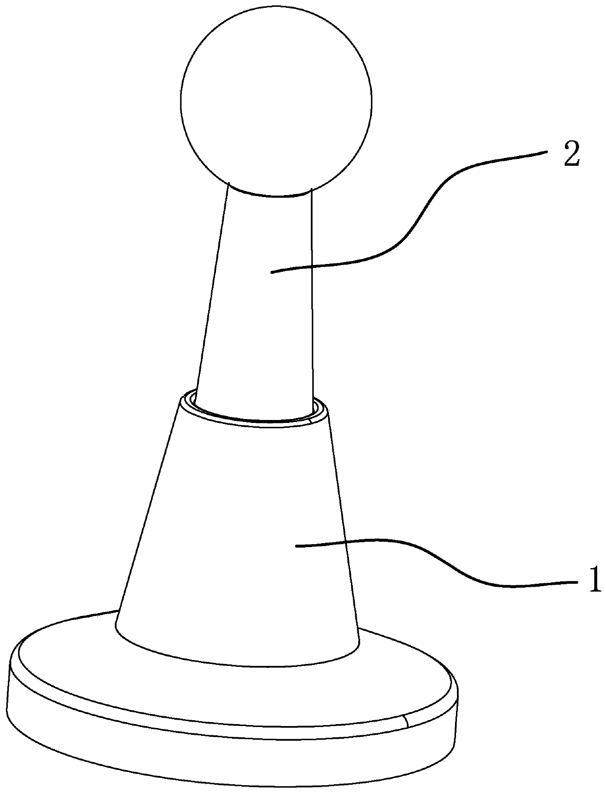
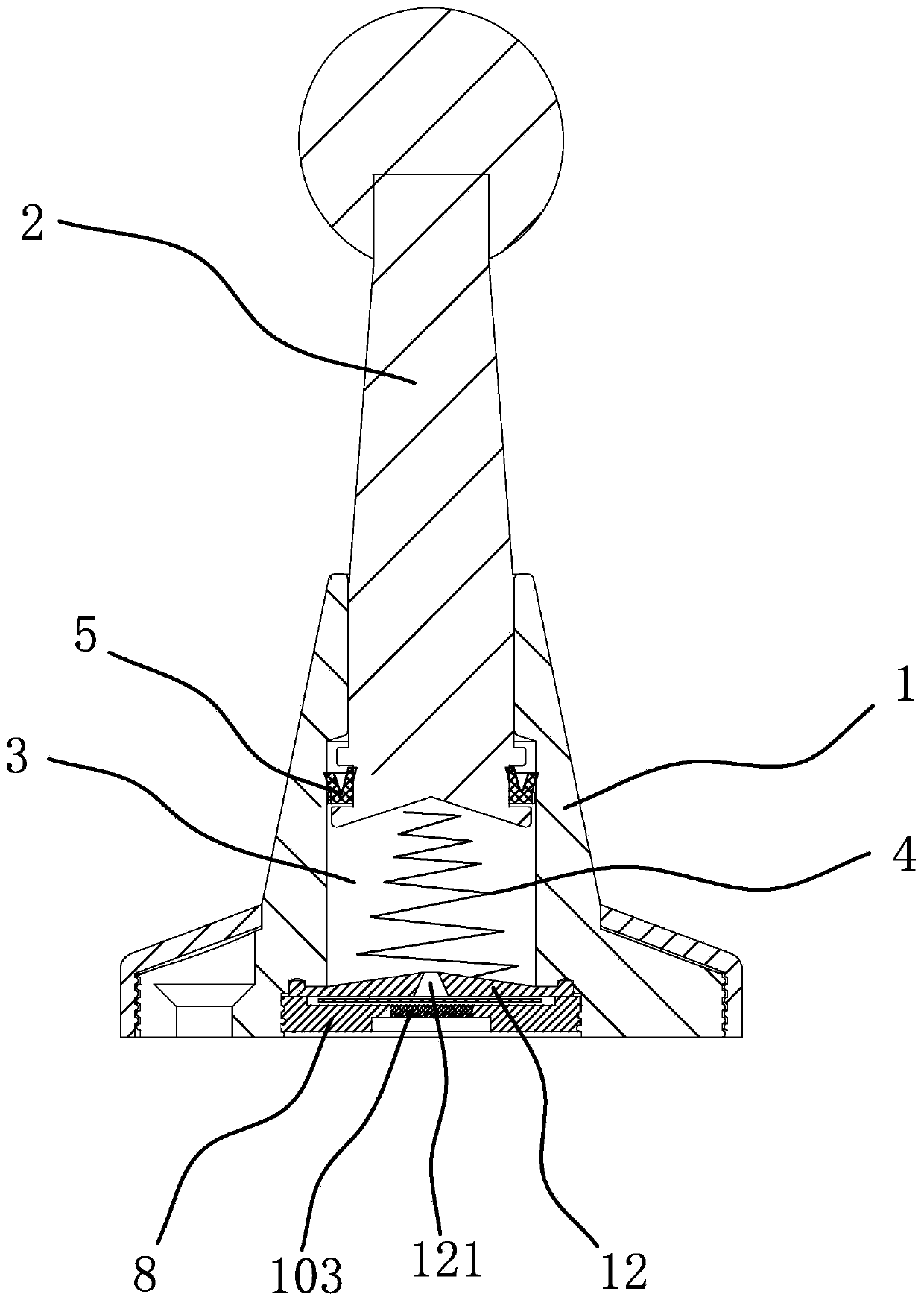
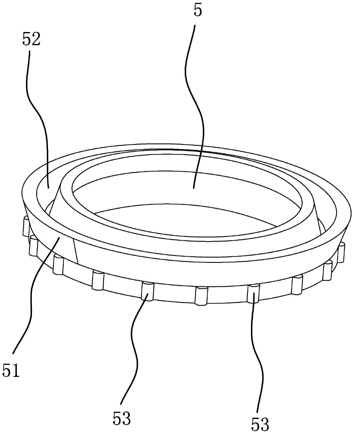
[0076] Such as Figure 1-5 As shown, the energy-absorbing bulletproof door bumper includes a seat body 1 and a columnar collision head 2. The seat body 1 has a stroke cavity 3, and the inner end of the collision head 2 is slidably fitted in the stroke cavity 3. The stroke cavity 3 passes through the collision The fit gap between the head 2 and the seat body 1 communicates with the outside world. A damping member 4 is provided between the inner end of the collision head 2 and the seat body 1 to prevent the collision head 2 from sliding into the seat body 1. The peripheral sleeve of the collision head 2 A sealing ring 5 is provided, and damping oil or lubricating oil is applied between the sealing ring 5 and the side wall of the stroke chamber 3 to make the work more stable. Between the head 2 and the inner side wall of the stroke chamber 3, when the collision head 2 slides toward the seat body 1, the sealing ring 5 can form a connecting air passage 6 with the collision head 2 o...
Embodiment 2
[0079] Such as Figure 7-11As shown, this embodiment is basically the same as Embodiment 1, except that the outer peripheral surface of the collision head 2 has a limit ring groove 21 extending in the circumferential direction, and the sealing ring 5 is located in the limit ring groove 21 and can move along the collision direction. The head 2 reciprocates in the axial direction, the sealing ring 5 is made of soft material and its outer edge is sealed against the inner wall of the stroke chamber 3, and the side of the sealing ring 5 close to the outer end of the collision head 2 has several circumferentially spaced As for the support blocks 54 , when the support blocks 54 abut against the inner sidewall of the limiting ring groove 21 , the space between two adjacent support blocks 54 forms the air passage 6 . By setting the limit ring groove 21 extending in the circumferential direction on the outer peripheral surface of the collision head 2, the seal ring 5 is located in the l...
Embodiment 3
[0082] Such as Figure 12-15 As shown, this embodiment is basically the same as Embodiment 2, the difference is that: the side wall of the limiting ring groove 21 near the outer end of the collision head 2 has a number of supporting teeth 22, when the sealing ring 5 and the supporting teeth 22 abut against The space between two adjacent supporting teeth 22 forms the air passage 6 . By setting the limit ring groove 21 extending in the circumferential direction on the outer peripheral surface of the collision head 2, the seal ring 5 is located in the limit ring groove 21 and can reciprocate along the axial direction of the collision head 2, and the seal ring 5 is The outer edge is made of soft material and is sealed against the inner side wall of the stroke chamber 3. There are a number of supporting teeth 22 on the side wall of the limit ring groove 21 near the outer end of the collision head 2, so that when the collision head 2 moves toward the inside of the seat body 1 When ...
PUM
 Abstract
Description
Claims
Application Information
 - R&D
- Intellectual Property
- Life Sciences
- Materials
- Tech Scout
- Unparalleled Data Quality
- Higher Quality Content
- 60% Fewer Hallucinations
Browse by: Latest US Patents, China's latest patents, Technical Efficacy Thesaurus, Application Domain, Technology Topic, Popular Technical Reports.
© 2025 PatSnap. All rights reserved.Legal|Privacy policy|Modern Slavery Act Transparency Statement|Sitemap|About US| Contact US: help@patsnap.com


