Headphone Control Structure

A control structure and earphone technology, which is applied in earpiece/earphone accessories, earphone mechanical/electronic switches, sensors, etc., can solve the problem of inconvenient earphone switching, and achieve the effect of convenient adjustment and user-friendliness

Active Publication Date: 2022-06-28
UBTECH ROBOTICS CORP LTD
View PDF10 Cites 0 Cited by
  • Summary
  • Abstract
  • Description
  • Claims
  • Application Information

AI Technical Summary

Problems solved by technology

[0003] The purpose of this application is to provide a headset control structure, aiming to solve the problem of inconvenient switching between different working states of the headset in the prior art

Method used


Image

  • Headphone Control Structure
  • Headphone Control Structure
  • Headphone Control Structure

Examples


specific Embodiment approach

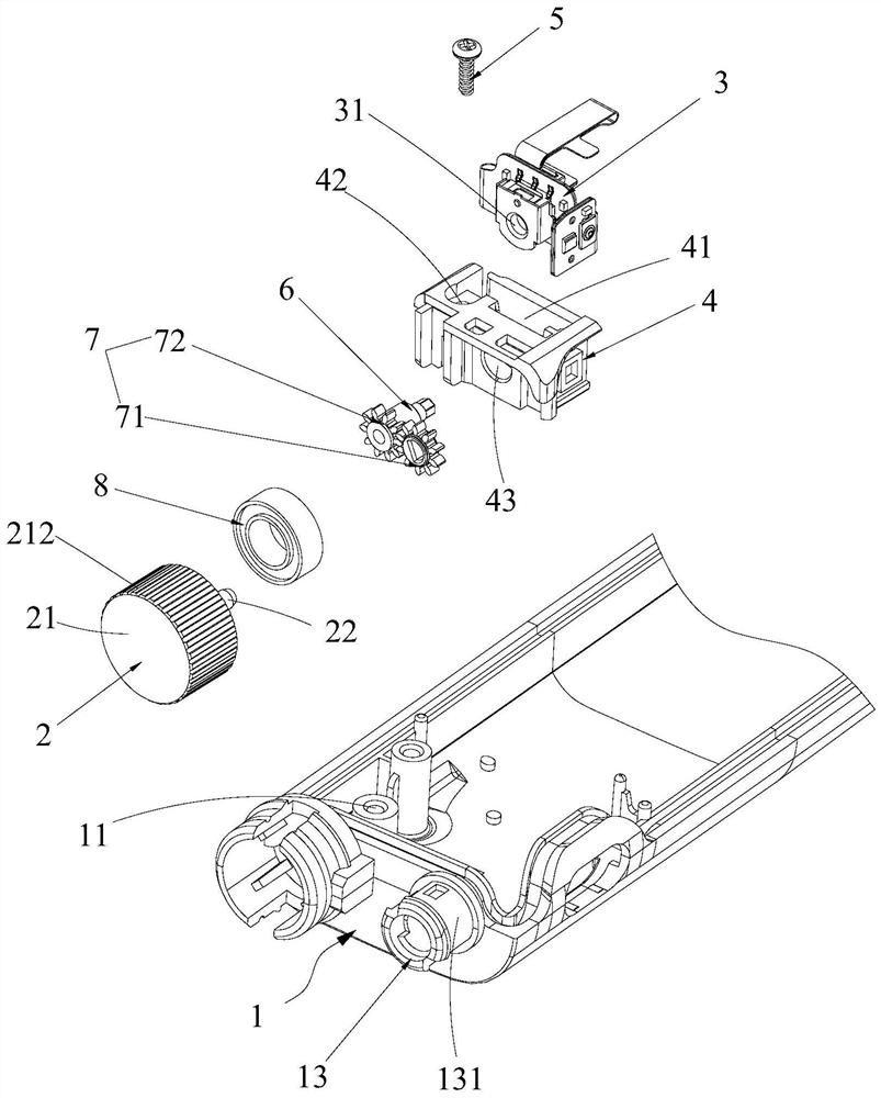
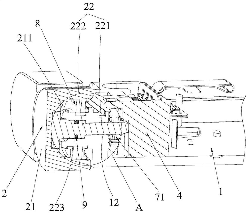
[0054] Further, see Figure 3-Figure 4 , as another specific embodiment of the earphone control structure provided by this application, the mounting frame 1 is provided with a rotating installation cylinder 13 surrounding the rotating hole 12 at the opening of the rotating hole 12; the rotating installation cylinder 13 is located in the rotating hole 12 away from the code The bearing 8 is installed on the outer wall of the rotating installation cylinder 13, the inner ring of the bearing 8 is connected with the rotating installation cylinder 13, and the screw cap 21 is connected with the outer ring of the bearing 8. The bearing 8 can make the rotating cap 21 only rotate after being stressed, and then drive the rotating shaft 22 to only rotate. The bearing 8 can improve the rotation stability of the rotating cap 21; The direct contact between the parts avoids the loss of the product caused by the friction between the parts during rotation, and improves the service life of the pr...


PUM


Abstract

The application discloses an earphone control structure, which includes: a mounting frame; a knob, which is rotatably mounted on the mounting frame; and an encoder, which is used to identify the rotation state of the knob to switch the working state of the earphone. The user rotates the knob so that the knob rotates relative to the mounting bracket. When the knob rotates, the encoder is triggered directly or through other transmission components; the encoder can identify the rotation state of the knob, and then the earphone switches to the corresponding working state. That is to say, it can be operated by rotating the knob. Compared with the button in the prior art with the micro switch, it needs to be pressed multiple times with a certain interval. It is more convenient to adjust the working state of the earphone, which greatly facilitates the use. By.

Description

technical field [0001] The present application relates to the field of earphone equipment, and in particular, to an earphone control structure. Background technique [0002] Headphones have evolved from a mere sound playback device to an electronic device with multiple modes, which can be switched between a variety of different functions. The existing switching method is to switch between the multi-functions by pressing the button with the micro switch. During the operation, the same action is repeated many times, and the switch to The desired working state, the action time is long, it is prone to errors, and the accuracy is poor, resulting in a poor user experience. SUMMARY OF THE INVENTION [0003] The purpose of the present application is to provide an earphone control structure, which aims to solve the problem of inconvenient switching between different working states of earphones in the prior art. [0004] For this purpose, the embodiment of the present application ...

Claims


Application Information

Patent Timeline
Patent Type & Authority Patents(China)
IPC IPC(8): H04R1/10
CPCH04R1/1041H04R2201/10
Inventor 韩峰熊友军
Owner UBTECH ROBOTICS CORP LTD
Why Eureka
Try Eureka