Electronic equipment and using method

A technology of electronic equipment and lens modules, which is applied in the field of photography, can solve problems that affect user experience, cannot ensure that the lens does not rotate, and restrict lens application scenarios, etc., to achieve the effect of convenient use and more aesthetic appearance

Inactive Publication Date: 2020-05-08
AAC OPTICS (CHANGZHOU) CO LTD
View PDF7 Cites 7 Cited by
  • Summary
  • Abstract
  • Description
  • Claims
  • Application Information

AI Technical Summary

Problems solved by technology

[0002] The current electronic equipment usually uses the driving mechanism to provide power and realize the functions of lifting and rotating the lens to any position through the transmission mechanism, rear camera, front camera, 360-degree ring shooting and scanning. The application scenarios are wide. However, due to the structure of the electronic device itself Due to the limitations of the lens, the lens can only rotate in one direction or when it is rising, it cannot ensure that the lens does not rotate, which restricts the application scenarios of the lens and affects the user experience.

Method used


Image

  • Electronic equipment and using method
  • Electronic equipment and using method
  • Electronic equipment and using method

Examples


Embodiment Construction

[0072] The present invention will be further described below in conjunction with the accompanying drawings and embodiments.

[0073] It should be noted that all directional indications (such as up, down, left, right, front, back, inside, outside, top, bottom...) in the embodiments of the present invention are only used to explain As shown in the figure), if the relative positional relationship between the various components, etc., if the specific posture changes, the directional indication will also change accordingly.

[0074] It should also be noted that when an element is referred to as being “fixed” or “disposed on” another element, the element may be directly on the other element or there may be an intervening element at the same time. When an element is referred to as being "connected to" another element, it can be directly connected to the other element or intervening elements may also be present.

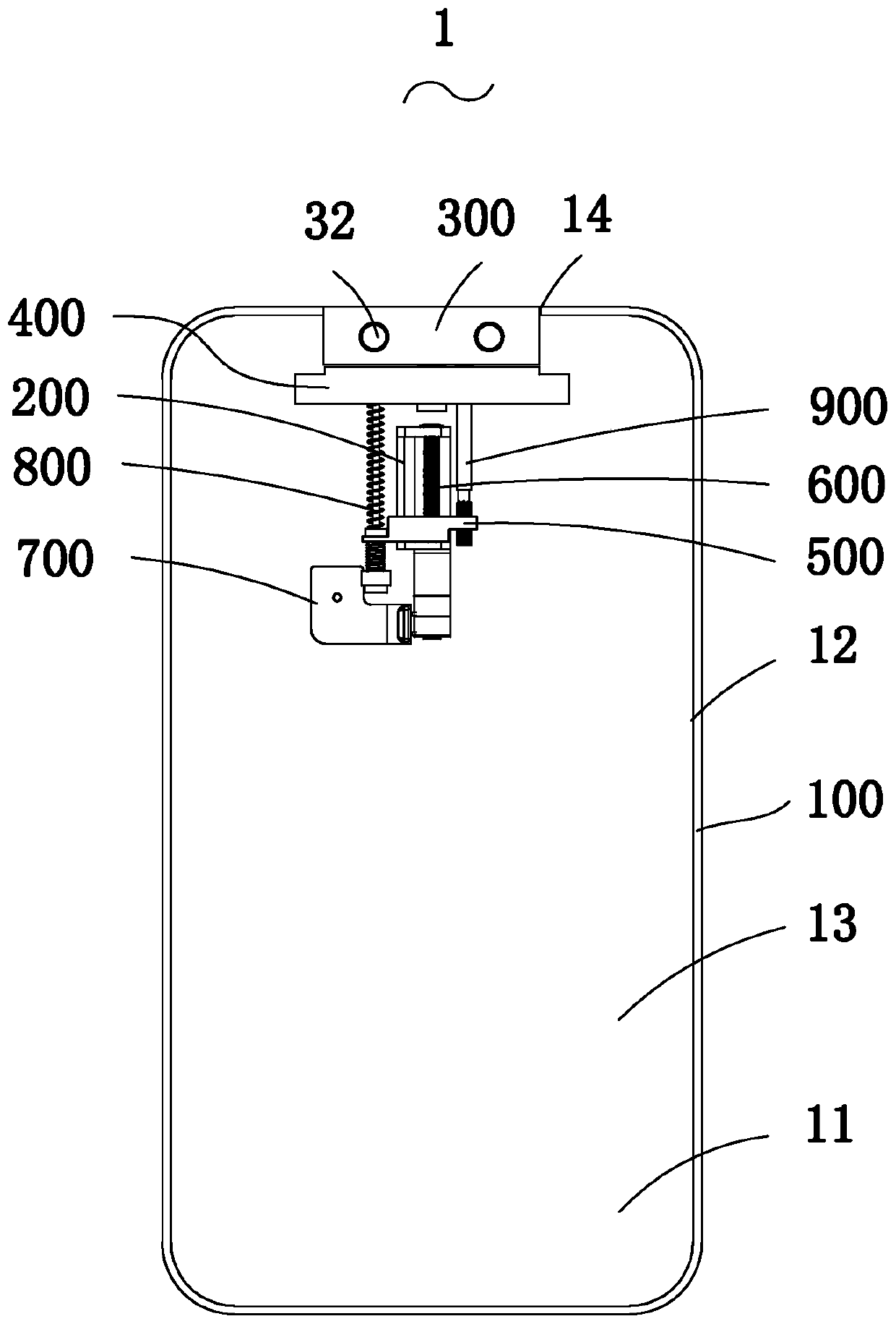
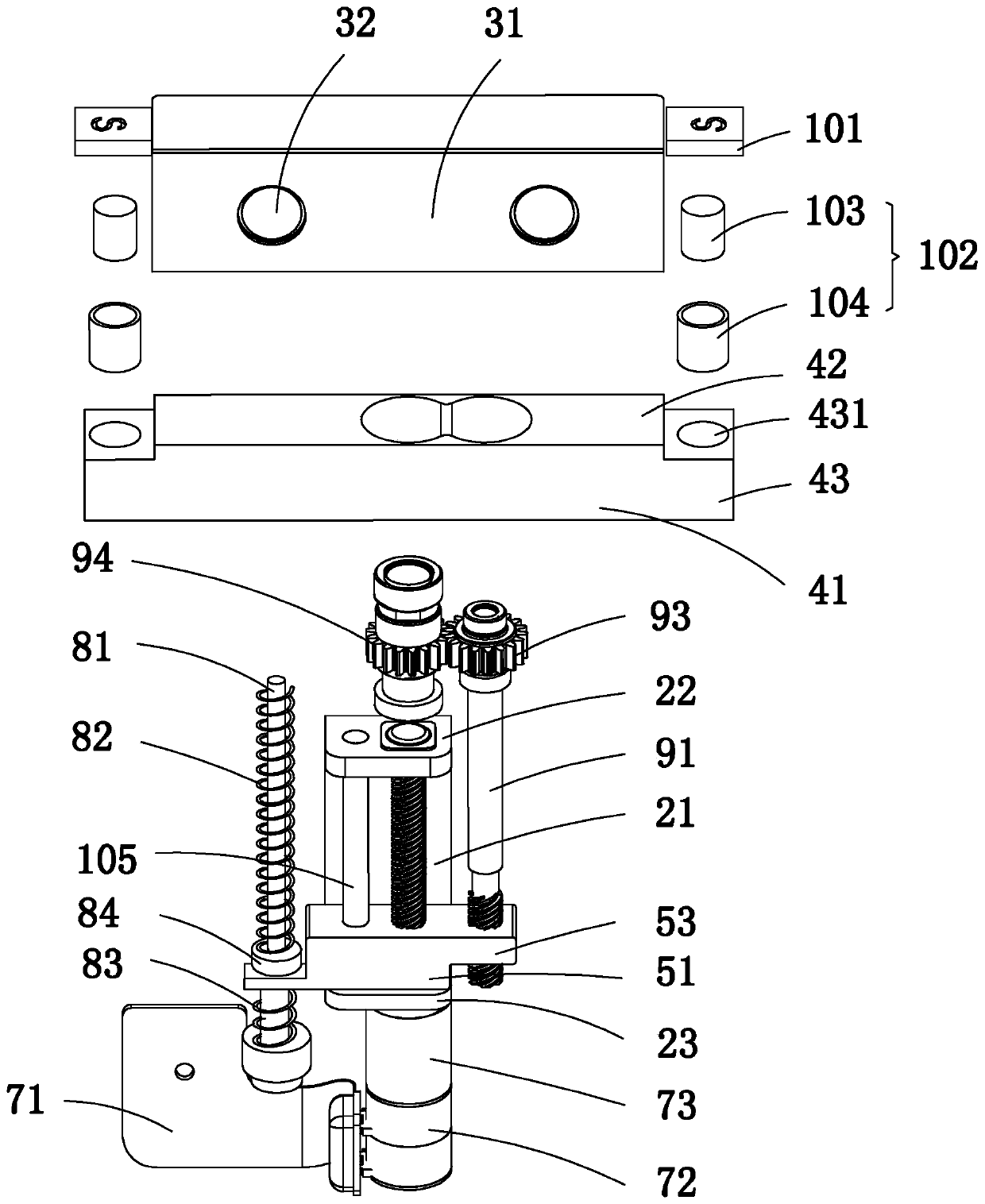
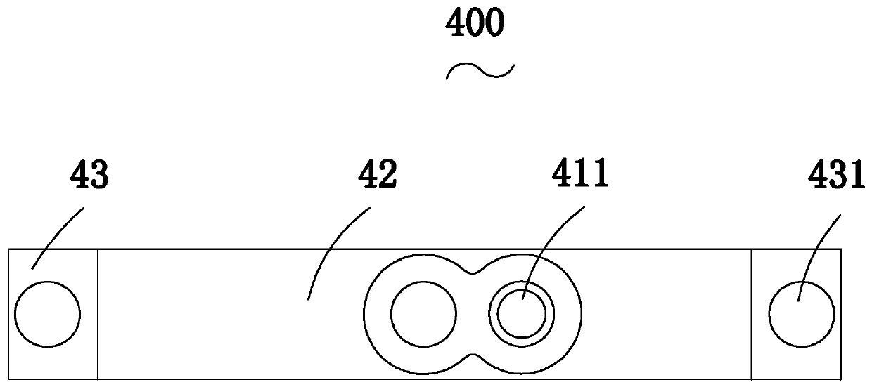
[0075] according to Figure 1-11 As shown, the embodiment of the pres...


PUM


Abstract

The invention provides electronic equipment and a using method. The electronic equipment comprises a back shell, a lens module, a supporting piece, a push block, a lead screw, a driving mechanism, a first transmission assembly, a second transmission assembly used for driving the lens module to rotate, a magnetic piece and an electromagnet. The supporting piece is rotationally connected with the lens module; the push block is sleeved on the lead screw and can move along the axial direction of the lead screw; the push block is in threaded fit with the lead screw; the driving mechanism is mountedon the back shell, and is connected with the lead screw, the first transmission assembly comprises a first guide rod, a first elastic piece, a second elastic piece and a shaft sleeve assembly. The shaft sleeve assembly comprises a shaft sleeve body, a shaft sleeve seat and a shaft sleeve cover; one end of the first guide rod is connected with the supporting piece; the first guide rod is in sliding connection with the push block through the shaft sleeve assembly, the first elastic piece is compressed between the supporting piece and the shaft sleeve base, the second elastic piece is compressedbetween the push block and the shaft sleeve cover, the magnetic piece and the electromagnet are opposite, one of the magnetic piece and the electromagnet is arranged on a surrounding wall, the otheris arranged on a stopping part, and the lens module can stretch out, draw back and rotate in two directions.

Description

【Technical field】 [0001] The invention relates to the field of camera technology, in particular to an electronic device with a camera adjustment device and a use method. 【Background technique】 [0002] The current electronic equipment usually uses the driving mechanism to provide power and realize the lens lifting and rotating to any position through the transmission mechanism, rear camera, front camera, 360-degree ring shooting and scanning, etc., and has a wide range of application scenarios. However, due to the structure of the electronic device itself Due to the limitations of the lens, the lens can only rotate in one direction or when it is rising, it cannot ensure that the lens does not rotate, which restricts the application scenarios of the lens and affects the user's experience. [0003] Therefore, it is necessary to develop an electronic device that can overcome the above-mentioned problems. 【Content of invention】 [0004] The first object of the present inventi...

Claims


Application Information

Patent Timeline
Patent Type & Authority Applications(China)
IPC IPC(8): H04M1/02
CPCH04M1/026H04M1/0264
Inventor 周帅宇王尧刘柯佳吴龙兴
Owner AAC OPTICS (CHANGZHOU) CO LTD
Why Eureka
Try Eureka