The connection structure of the main shaft and the speed-increasing gearbox of the wind turbine and its optimization design method

A technology for connecting structures and gearboxes, which is applied in mechanical equipment, wind power generation, wind turbines, etc., can solve problems such as difficulty in bolt arrangement and limitation of large-scale units, reduce installation difficulty and unit design difficulty, ensure torque transmission effect, The effect of reducing the number of bolts

Active Publication Date: 2021-03-12
TAIYUAN HEAVY IND
View PDF7 Cites 0 Cited by
  • Summary
  • Abstract
  • Description
  • Claims
  • Application Information

AI Technical Summary

Problems solved by technology

The current flange connections are all flat flange connections, and the torque transmission is mainly realized by the static friction force provided by the bolt pre-tightening force to compress the flange surface, but with the increase of rated power and the lengthening of blades, the torque is often very large , Relying on the friction force of the plane flange to transmit torque requires a lot of bolts, and the structure needs to be enlarged to a certain extent. However, due to the space constraints such as the diameter of the main shaft, the bolt arrangement becomes difficult, which brings great difficulties to the enlargement of the unit. limit

Method used


Image

  • The connection structure of the main shaft and the speed-increasing gearbox of the wind turbine and its optimization design method
  • The connection structure of the main shaft and the speed-increasing gearbox of the wind turbine and its optimization design method
  • The connection structure of the main shaft and the speed-increasing gearbox of the wind turbine and its optimization design method

Examples


Embodiment Construction

[0044] In order to make the purpose, technical solution and advantages of the present invention clearer, the technical solution of the present invention will be clearly and completely described below in conjunction with specific embodiments of the present invention and corresponding drawings. Apparently, the described embodiments are only some of the embodiments of the present invention, but not all of them. Based on the embodiments of the present invention, all other embodiments obtained by persons of ordinary skill in the art without making creative efforts fall within the protection scope of the present invention.

[0045] The technical solutions provided by the embodiments of the present invention will be described in detail below in conjunction with the accompanying drawings.

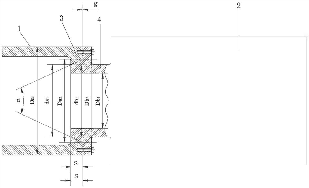
[0046] In the first aspect, the embodiment of the present invention provides a connection structure between the main shaft of the wind turbine and the speed-up gearbox, as shown in the attached fi...


PUM


Abstract

The invention discloses a connecting structure for a spindle and a step-up gear box of a wind turbine generator and an optimization design method of the connecting structure. In the connecting structure, an end flange of the spindle is of an inner cone structure with the inner diameters gradually reduced from outside to inside, and the end of an input shaft of the step-up gear box is of a conic structure matched with the inner cone structure. The large diameter of the end flange is 97%-99% of the large diameter of the end of the input shaft, the small diameter of the end flange is 97%-99% of the small diameter of the end of the input shaft, and the conic face angles and lengths of the end flange and the end of the input shaft are the same. After the end flange is inserted into the end of the input shaft, the end flange and the end of the input shaft are fastened through bolts. According to the connecting structure for the spindle and the step-up gear box of the wind turbine generator and the optimization design method of the connecting structure, the friction force of the contact face is large, the number of the bolts needed during fastening is reduced, mounting difficulty and unitdesign difficulty are reduced, the design optimization efficiency of the unit is improved, and the torque transmission effect is guaranteed.

Description

technical field [0001] The invention relates to the technical field of wind power generation equipment, in particular to a connection structure between a main shaft and a speed-increasing gearbox of a wind power unit and an optimization design method thereof. Background technique [0002] With the increasing energy consumption and the increasing demand for environmental protection, the development of renewable new energy is getting more and more attention. Among them, wind power is one of the fastest growing new energy sources, and the design of wind turbines has become a crucial technology in the wind energy industry. . In wind turbines with step-up gearboxes, the main shaft needs to transmit torque to the step-up gearbox. A reliable connection without gaps is required between the two, usually in the form of a shrink disc or a flange. Shrink disks are usually used in smaller megawatt wind turbines, and flange connections are used to further shorten the length of the trans...

Claims


Application Information

Patent Timeline
Patent Type & Authority Patents(China)
IPC IPC(8): F16D1/05F16D1/033F03D15/00G06F30/20G06F30/17G06F119/14
CPCF16D1/033F16D1/05Y02E10/72
Inventor 王晓东王建华王春乐吴建华姜宏伟王浩朱少辉丁欣石磊范润驰
Owner TAIYUAN HEAVY IND
Why Eureka
Try Eureka