
Speed control device for vehicle

A speed control device and vehicle technology, applied in the direction of control device, speed/acceleration control, vehicle maintenance, etc., can solve the problems of increasing driver fatigue, cumbersome and complicated operation, reducing vehicle stability, etc., to ensure safe driving and operation. Simple and convenient, the effect of ensuring stability

Active Publication Date: 2020-05-08
湖南汉坤实业有限公司
View PDF6 Cites 0 Cited by
  • Summary
  • Abstract
  • Description
  • Claims
  • Application Information

AI Technical Summary

Problems solved by technology

[0002] Automobile, that is, a vehicle that can be driven by its own power and does not need to be erected according to rails or electricity. In a broad sense, a vehicle with four wheels is generally called a vehicle. With the continuous development of society and people's living standards With the continuous improvement of automobiles, the demand for automobiles is increasing, and the functions of automobiles are also increasing. However, when some automobiles are driven for a long time, it is not particularly convenient to control their speed. Therefore, a speed control device for vehicles growing demand
[0003] In the field of automobiles, when some vehicles currently used are driven on high speed for a long time, it is not very convenient to control the speed of the vehicle, and there is no voice recognition system, which not only increases the fatigue of the driver, but also reduces the fatigue of the vehicle during driving. Stability, and some vehicles cannot realize the automatic cleaning of the brake pedal and the accelerator pedal. In this way, when there is water on the outside of the brake pedal and the accelerator pedal in winter, the risk of freezing and slipping will easily occur when stepping on it, and the brake pedal and the accelerator pedal There will also be a risk of failure to reset normally. In the case of mud attached to the outside of the brake pedal and the accelerator pedal, there will also be a risk of slipping when stepping on it, so that the safe driving of the vehicle cannot be guaranteed. Even though some vehicles are equipped with There is a speech recognition module, but when the speech recognition module is damaged, it is particularly inconvenient to disassemble and maintain it, and the operation is cumbersome and complicated. Therefore, a vehicle speed control device is proposed to solve the above problems

Method used


Image

  • Speed control device for vehicle
  • Speed control device for vehicle
  • Speed control device for vehicle

Examples


Embodiment 1

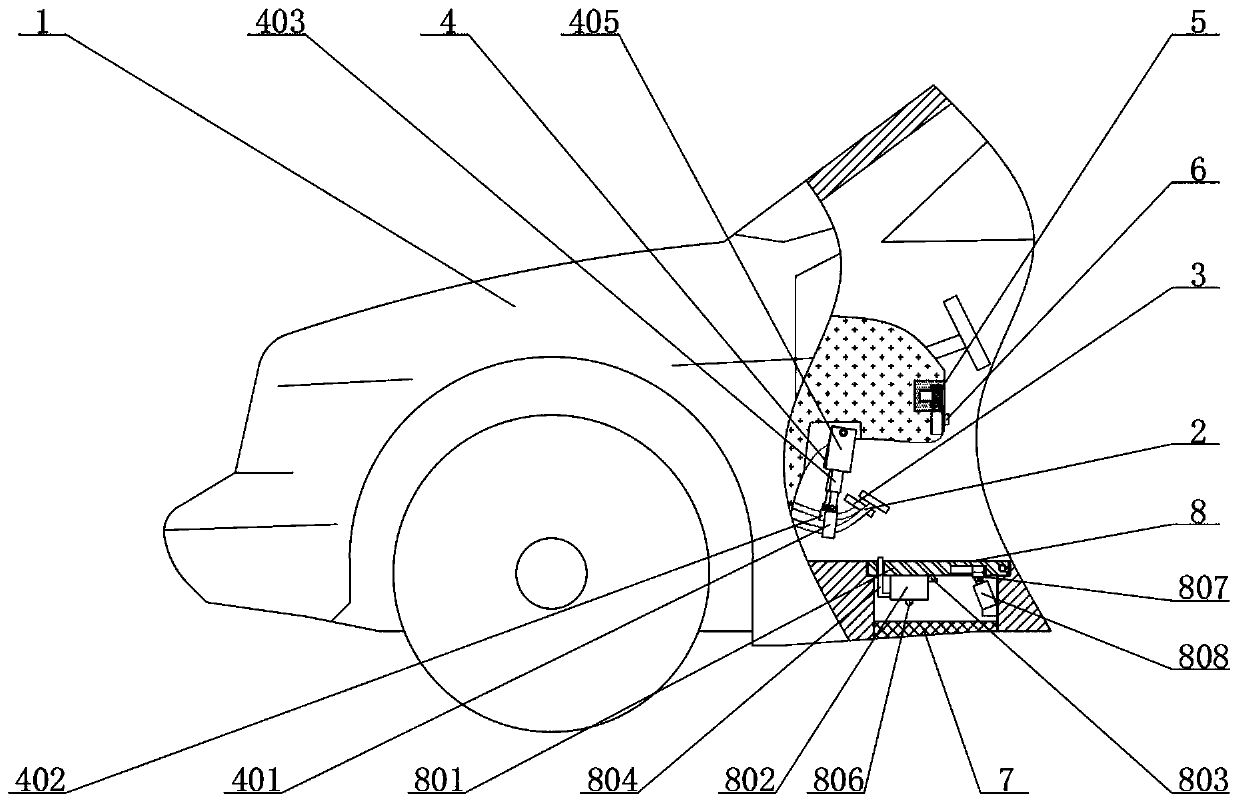
[0030] see figure 1 , figure 2 , Figure 4 , Figure 5 , Figure 7 and Figure 8 , the present invention provides a technical solution:

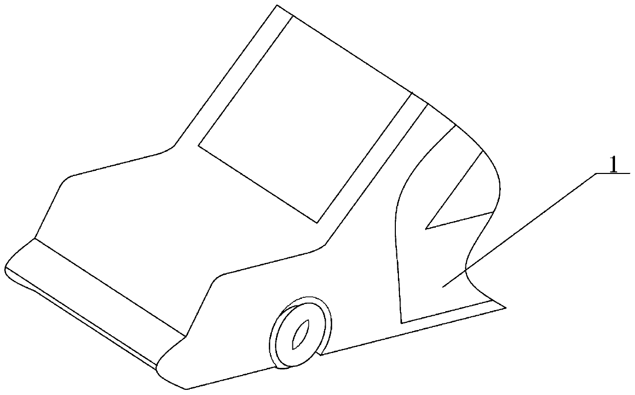
[0031]A speed control device for a vehicle, comprising a vehicle body 1, a speed control device 4, a positioning device 5 and a processing device 8, the inner side of the vehicle body 1 is slidingly connected with a brake pedal 2 and an accelerator pedal 3 arranged front and rear, and the top of the brake pedal 2 is provided There is a speed control device 4, and the speed control device 4 is fixedly connected with the brake pedal 2 and the accelerator pedal 3. The speed control device 4 includes a first fixed block 401, a second fixed block 402, a first electric telescopic rod 403, a slide block 404, The sleeve rod 405 and the first spring 406, the outer side of the brake pedal 2 is fixedly connected with the first fixed block 401, the outer side of the accelerator pedal 3 is fixedly connected with the second fixed block 402, the top ...

Embodiment 2

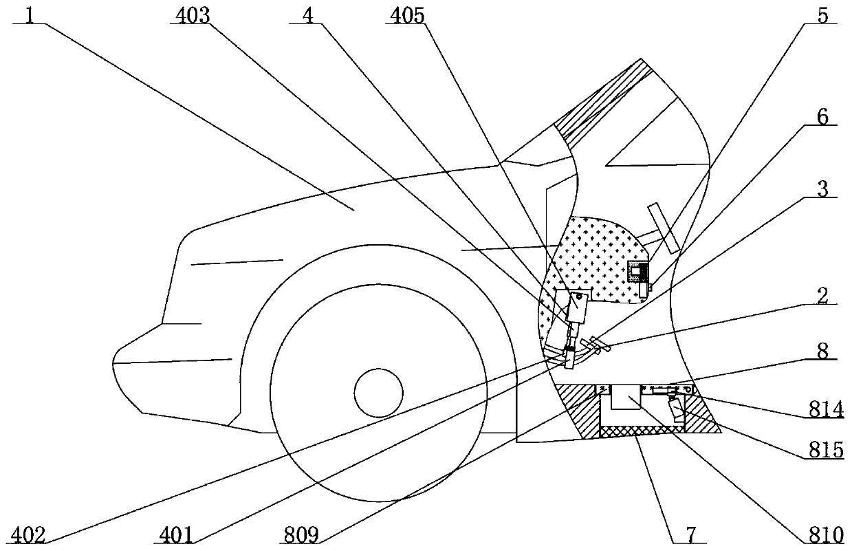
[0035] see figure 1 , image 3 , Figure 4 , Figure 6 , Figure 7 and Figure 9 , the present invention provides a technical solution:

[0036] A speed control device for a vehicle, comprising a vehicle body 1, a speed control device 4, a positioning device 5 and a processing device 8, the inner side of the vehicle body 1 is slidingly connected with a brake pedal 2 and an accelerator pedal 3 arranged front and rear, and the top of the brake pedal 2 is provided There is a speed control device 4, and the speed control device 4 is fixedly connected with the brake pedal 2 and the accelerator pedal 3. The speed control device 4 includes a first fixed block 401, a second fixed block 402, a first electric telescopic rod 403, a slide block 404, The sleeve rod 405 and the first spring 406, the outer side of the brake pedal 2 is fixedly connected with the first fixed block 401, the outer side of the accelerator pedal 3 is fixedly connected with the second fixed block 402, the top ...


PUM


Abstract

The invention relates to the technical field of automobiles. The invention relates to a speed control device for a vehicle. The speed control device for a vehicle comprises a vehicle body, a speed control device, a positioning device and a processing device, wherein a brake pedal and an accelerator pedal which are arranged front and back are slidably connected to the inner side of the vehicle body; the speed control device is arranged at the top end of the brake pedal; the speed control device is fixedly connected with the brake pedal and the accelerator pedal; the speed control device is rotationally connected with the vehicle body through a rotating shaft; the positioning device is arranged on the right side of the top end of the speed control device; and a controller is arranged at thebottom end of the right side of the positioning device. In the present invention, a sleeve rod is arranged, through the rotary connection of a first electric telescopic rod, a first fixed block and asecond fixed block, the rotary connection of the sleeve rod and the vehicle body and the elastic force of the first spring to the sliding block, under the control of the controller over the first electric telescopic rod and the voice recognition module, the speed of the vehicle body is simply controlled, the fatigue degree of a driver is reduced, and the stability of the vehicle in the driving process is guaranteed.

Description

technical field [0001] The invention relates to the technical field of automobiles, in particular to a vehicle speed control device. Background technique [0002] Automobile, that is, a vehicle that can be driven by its own power and does not need to be erected according to rails or electricity. In a broad sense, a vehicle with four wheels is generally called a vehicle. With the continuous development of society and people's living standards With the continuous improvement of automobiles, the demand for automobiles is increasing, and the functions of automobiles are also increasing. However, when some automobiles are driven for a long time, it is not particularly convenient to control their speed. Therefore, a speed control device for vehicles demand is growing. [0003] In the field of automobiles, when some vehicles currently used are driven on high speed for a long time, it is not very convenient to control the speed of the vehicle, and there is no voice recognition syst...

Claims


Application Information

Patent Timeline
IPC IPC(8): B60K31/00B60S1/64
CPCB60K31/00B60K2031/0091B60S1/64
Inventor 康望才
Owner 湖南汉坤实业有限公司
Learn More