


Quick Research
Generate reliable direction feasibility study reports for your R&D in just a few steps.

Technical Q&A
Discover and master advanced knowledge NOW. Basics, ideas, possibilities, all at once.

Find Solutions
As an expert in R&D theories, this can generate solutions to your technical problems instantly.

Evaluate Feasibility
Analyze your overall solution with one click, know your potential R&D risks in advance.

Monitor Landscape
Get weekly tech updates, stay abreast of the latest tech innovations and key insights.
Glass bottle turning mechanism
A steering mechanism and glass bottle technology, which is applied in the direction of conveyor objects, transportation and packaging, etc., can solve the problems of difficult conveyor belt steering and conveyor belt difficulty, and achieve a convenient position for the inlet and outlet, reduce shaking, and facilitate The effect of steering
- Summary
- Abstract
- Description
- Claims
- Application Information
AI Technical Summary
Problems solved by technology
Method used
Image

Examples
Embodiment 1
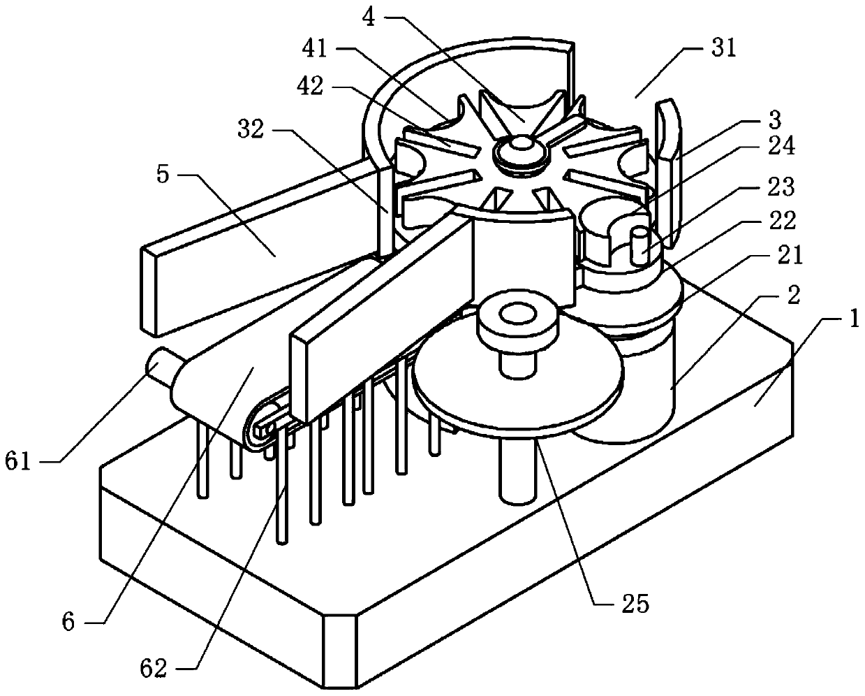
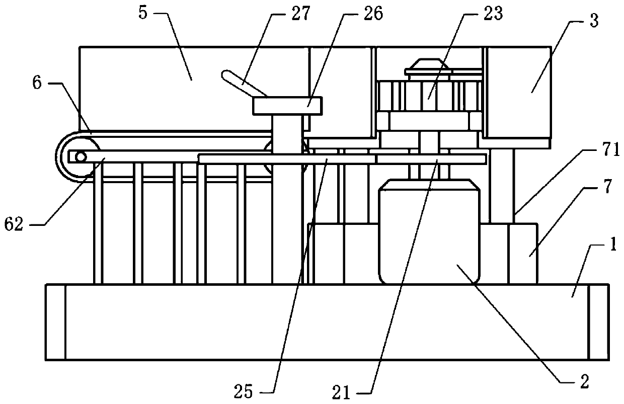
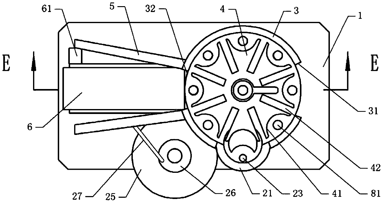
[0036] Basic as attached figure 1 And attached figure 2 As shown, a glass bottle steering mechanism includes a workbench 1. A frame 62 is installed on the left side of the workbench 1 through fastening bolts. A conveyor belt 6 driven by a drive motor 61 is installed on the frame 62. The drive motor 61 passes Fastening bolts are installed on the frame 62 . The right side of the workbench 1 is equipped with a driving part. In this embodiment, the driving part is a single-phase motor 2. The single-phase motor 2 is fixed on the workbench 1 by fastening bolts. The output shaft of the single-phase motor 2 is fixed by coaxial welding. There is a rotating disc 22, on which a locking disc 24 is coaxially fixed by fastening bolts, and a cylindrical pin 23 is welded and fixed at the center of the rotating disc 22.
[0037] as attached Figure 4 As shown, the workbench 1 is provided with a negative pressure assembly. In this embodiment, the negative pressure assembly includes a negati...
Embodiment 2
[0047] The difference between embodiment two and embodiment one is that, as attached Figure 5 As shown, a connecting plate 101 is coaxially welded and fixed on the support shaft 10, and the connecting plate 101 is located at the discharge port 31. Its circumferential direction is provided with several pushing plates 43, and the pushing plates 43 are respectively located in the grooves 41, and the pushing plates 43 are horizontally slidably connected with the sheave 4, and an elastic member is arranged between the pushing plate 43 and the sheave 4. In this embodiment, the elastic Part is spring 44, and the two ends of spring 44 are respectively welded and fixed on sheave 4 and push plate 43, and second permanent magnet 45 is fixed on push plate 43 by fastening bolt, first permanent magnet 102 and second permanent magnet 45 The opposite side has opposite magnetic poles.
[0048] The specific implementation process is as follows:
[0049] When the sheave 4 pushes the glass bot...
PUM
 Abstract
Description
Claims
Application Information
 - R&D Engineer
- R&D Manager
- IP Professional
- Industry Leading Data Capabilities
- Powerful AI technology
- Patent DNA Extraction
Browse by: Latest US Patents, China's latest patents, Technical Efficacy Thesaurus, Application Domain, Technology Topic, Popular Technical Reports.
© 2024 PatSnap. All rights reserved.Legal|Privacy policy|Modern Slavery Act Transparency Statement|Sitemap|About US| Contact US: help@patsnap.com