
Wireless charging device capable of automatically matching charging position and wireless charging method

A wireless charging and charging position technology, applied in battery circuit devices, circuit devices, current collectors, etc., can solve the problems of small charging area, easy deviation of placement, and low charging efficiency, so as to improve the charging area and improve the experience. The effect of improving the charging efficiency

Pending Publication Date: 2020-04-24
苏州蓝沛无线通信科技有限公司
View PDF0 Cites 0 Cited by
  • Summary
  • Abstract
  • Description
  • Claims
  • Application Information

AI Technical Summary

Problems solved by technology

[0003] In view of the above-mentioned shortcomings of the prior art, the object of the present invention is to provide a wireless charging device and a wireless charging method that automatically matches the charging position, which are used to solve the problems of the wireless charging device in the prior art that the charging area is small and placed The position is easy to deviate, the alignment between the wireless charging coil and the receiving end coil is low, and the charging efficiency is not high, etc.

Method used


Image

  • Wireless charging device capable of automatically matching charging position and wireless charging method
  • Wireless charging device capable of automatically matching charging position and wireless charging method
  • Wireless charging device capable of automatically matching charging position and wireless charging method

Examples


Embodiment 2

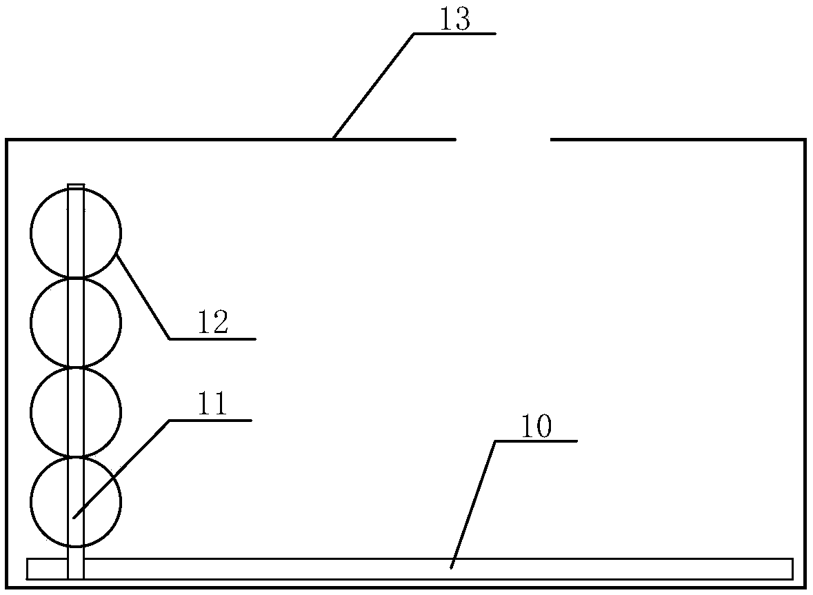
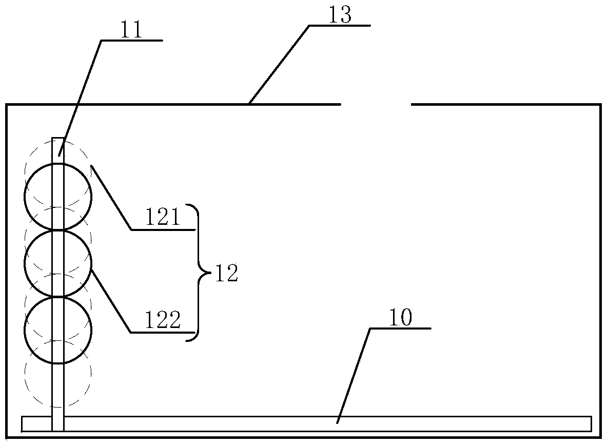
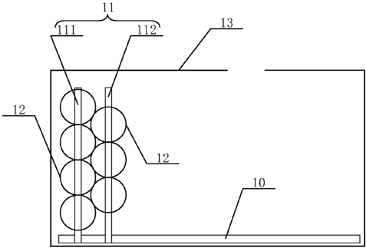
[0057] read on Figure 1 to Figure 4 refer to Figure 5 ,, the present invention also provides a wireless charging method, the wireless charging method includes the following steps:

[0058] 1) Provide a wireless charging device that automatically matches the charging position as described in Embodiment 1;

[0059] 2) Place the device to be charged on the wireless charging device that automatically matches the charging position, and then slide the fixing rod to adjust the position of the wireless charging coil until the wireless charging coil moves to the optimal charging position;

[0060] 3) Allocating the corresponding wireless charging coil to charge the device to be charged according to the feedback signal.

[0061] As an example, for the specific structure of the wireless charging device that automatically matches the charging position provided in step 1), please refer to

Embodiment 1

[0062] Embodiment 1 will not be repeated here.

[0063] As an example, in step 2), it is judged according to the charging efficiency whether the wireless charging coil 12 is consistent with the optimal charging position; specifically, the wireless charging coil 12 can be used to charge the device to be charged for the first time. At the same time, fine-tune the position of the wireless charging coil 12 until the position with the highest charging efficiency is found, which is the optimal charging position.

[0064] As an example, in step 3), the wireless charging coil 12 with the strongest feedback signal is used to charge the device to be charged. At this time, if there are multiple wireless charging coils 12 with the strongest feedback signals, use the multiple wireless charging coils 12 with the strongest feedback signals to charge the device to be charged.

[0065] As an example, step 3) further includes the step of returning the fixed rod 11 to the initial position, that...


PUM


Abstract

The invention provides a wireless charging device capable of automatically matching a charging position and a wireless charging method. The wireless charging device capable of automatically matching the charging position comprises a guide rail and a fixing rod. One end of the fixing rod is arranged in the guide rail and can slide along the guide rail. The device further comprises a plurality of wireless charging coils which are fixed on the fixing rod. According to the wireless charging device capable of automatically matching the charging position, accurate alignment of the wireless chargingcoils and the receiving coils in the to-be-charged equipment can be realized; the rechargeable area can be improved; and the charging efficiency can be greatly improved, so that the user experience is improved.

Description

technical field [0001] The invention belongs to the technical field of wireless charging, and in particular relates to a wireless charging device and a wireless charging method for automatically matching charging positions. Background technique [0002] With the development and application of today's wireless charging technology, more and more wireless charging products have entered the lives of ordinary people, and wireless chargers have become more and more widely accepted and used by the public. The wireless charging coil in the existing wireless charging device is generally fixed on the base to work, and the user puts the device to be charged (for example, a mobile phone, etc.) on it to perform wireless charging. However, since the existing wireless charging coil is fixed on the base and cannot be moved, there are problems when charging the device to be charged, the charging area is small, the placement position is easy to deviate, the alignment of the wireless charging ...

Claims


Application Information

Patent Timeline
Patent Type & Authority Applications(China)
IPC IPC(8): H02J50/10H02J50/90H02J7/00
CPCH02J7/0044H02J50/10H02J50/90
Inventor 吴迪范存赟陶利明林涛李建法
Owner 苏州蓝沛无线通信科技有限公司
Learn More