Constant draft rate unwinding method and device for passive unwinding warp beam
A draft rate and warp beam technology is applied in the field of constant draft rate unwinding methods and devices for passive unwinding warp beams, which can solve the problems of different yarn draft rates, different draft rates, and yarn residues. , to achieve the effect of stable operation process, balanced drafting effect and concise control program.
- Summary
- Abstract
- Description
- Claims
- Application Information
AI Technical Summary
Problems solved by technology
Method used
Image
Examples
Embodiment 1
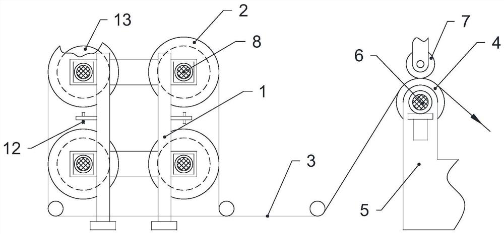
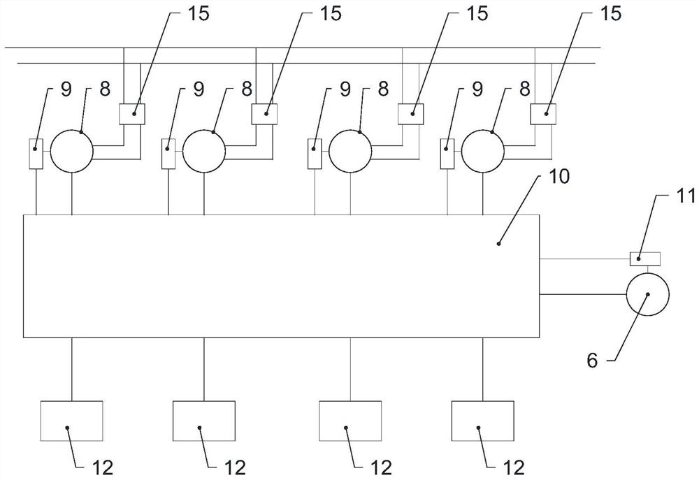
[0032] In order to clearly explain the specific implementation process of this embodiment, this embodiment borrows the attached figure 1 and 2 Describe the specific implementation process in detail.
[0033]The constant draft rate unwinding method of the passive unwinding type warp beam includes adopting brake motors 8 corresponding to the warp beams 2 one-to-one to control the speed of each warp beam 2, and connecting each brake motor 8 to the controller 10 electrically. Sexual connection, the speed of each braking motor 8 is controlled by the controller 10, and the independent traction roller 4 is used as the driving roller to draw the yarn 3 on each warp beam 2, and the traction roller 4 is driven by the main motor 6 to rotate. The main motor 6 is electrically connected to the controller 10 and feeds back the rotation speed to the controller 10 through the second encoder 11. The controller 10 is based on the rotation speed M of the main motor 6, the transmission ratio Q be...
Embodiment 2
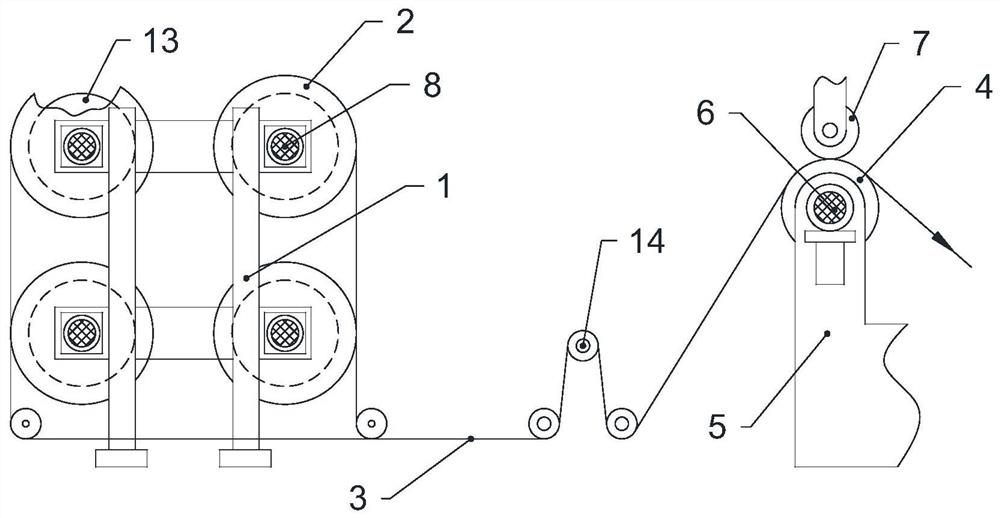
[0039] In order to clearly explain the specific implementation process of this embodiment, this embodiment borrows the attached image 3 and 4 Describe the specific implementation process in detail.
[0040] The constant draft rate unwinding method of the passive unwinding type warp beam includes adopting brake motors 8 corresponding to the warp beams 2 one-to-one to control the speed of each warp beam 2, and connecting each brake motor 8 to the controller 10 electrically. connected, the controller 10 controls the speed of each brake motor 8, adopts an independent traction roller 4 as a driving roller to traction the yarn 3 on each warp beam 2, and the traction roller 4 is connected with a main motor 6 , the rotating speed of main motor 6 feeds back to controller 10 through second encoder 11, adopts tension sensor 14 to carry out tension detection to the yarn sheet after each warp beam 2 merges and feeds back to controller 10, by controller 10 according to real-time tension a...
Embodiment 3
[0044] Such as figure 1 and figure 2 The shown passive unwinding warp beam constant draft rate unwinding device includes a creel 1, four warp beams 2 rotatably connected to the warp beam 1, and yarns 3 for drawing the warp beam 2 traction roller 4, the traction roller 4 is rotatably connected on the traction frame 5, the present invention has no specific restrictions on the structure of the traction frame 5, as long as the traction roller 4 can be fixed and does not interfere with the movement of the yarn, the traction roller 4 is controlled by the main motor 6 Drive and rotate, the traction frame 5 is also rotatably connected with the pressure roller 7 abutting against the traction roller 4, and the warp beam frame 1 is fixedly connected with a one-to-one correspondence with the warp beam 2, which is used to apply the pressure roller 7 to the warp beam 2. Power braking motors 8, each braking motor 8 is connected to a controller 10 through a one-to-one corresponding first en...
PUM
 Abstract
Description
Claims
Application Information
 - R&D Engineer
- R&D Manager
- IP Professional
- Industry Leading Data Capabilities
- Powerful AI technology
- Patent DNA Extraction
Browse by: Latest US Patents, China's latest patents, Technical Efficacy Thesaurus, Application Domain, Technology Topic, Popular Technical Reports.
© 2024 PatSnap. All rights reserved.Legal|Privacy policy|Modern Slavery Act Transparency Statement|Sitemap|About US| Contact US: help@patsnap.com


