


Quick Research
Generate reliable direction feasibility study reports for your R&D in just a few steps.

Technical Q&A
Discover and master advanced knowledge NOW. Basics, ideas, possibilities, all at once.

Find Solutions
As an expert in R&D theories, this can generate solutions to your technical problems instantly.

Evaluate Feasibility
Analyze your overall solution with one click, know your potential R&D risks in advance.

Monitor Landscape
Get weekly tech updates, stay abreast of the latest tech innovations and key insights.
Method and device for linkage between radar and dome camera
A ball camera and radar technology, applied in the field of radar and ball camera linkage, can solve the problems of complicated operation, unable to guarantee measurement accuracy, unable to guarantee the linkage accuracy of radar and ball camera, etc., to achieve accurate target monitoring and improve the effect of linkage accuracy.
- Summary
- Abstract
- Description
- Claims
- Application Information
AI Technical Summary
Problems solved by technology
Method used
Image

Examples
Embodiment 1
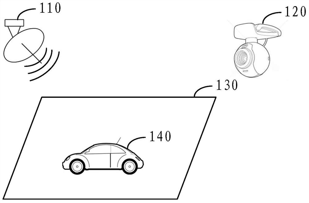
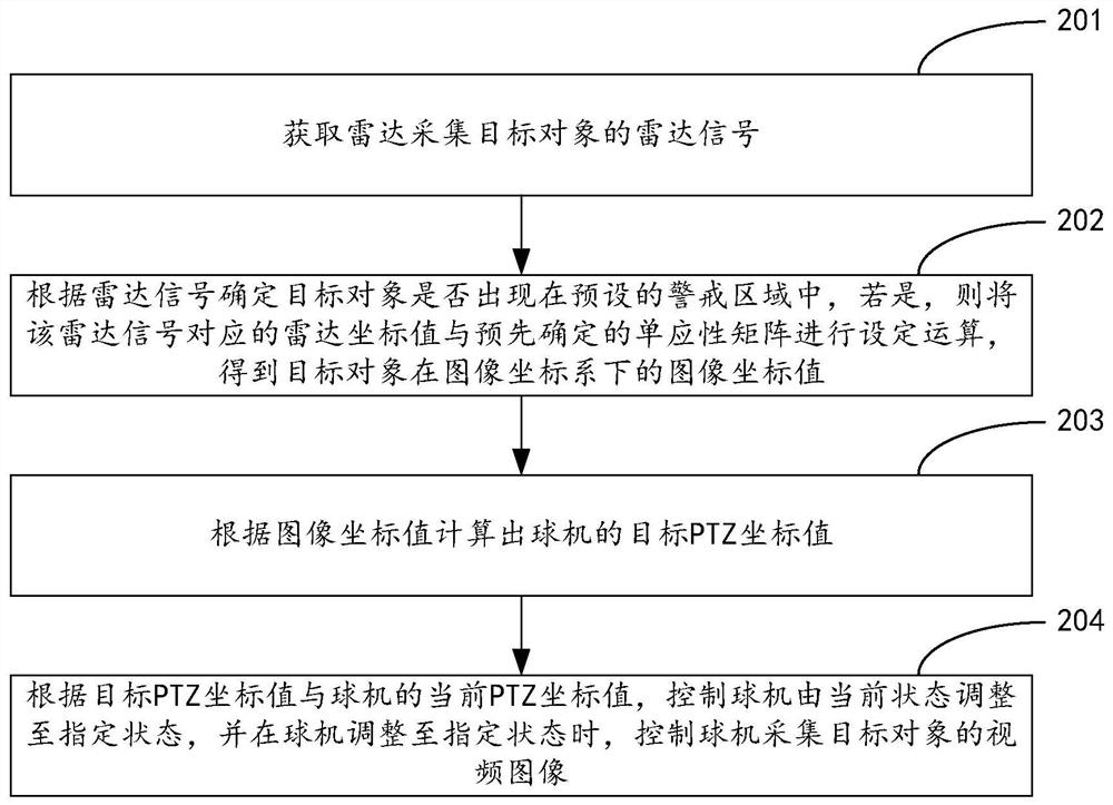
[0115] See figure 2 , is a flow chart of an embodiment of a method for linkage between a radar and a ball camera shown in an exemplary embodiment of the present application. The method is described above figure 1 Based on the application scenario shown, the following steps may be included:
[0116] Step 201: Obtain the radar signal of the radar acquisition target object.
[0117] by figure 1 The illustrated application scenario is taken as an example. In the embodiment of the present application, the radar signal of the target object 140 collected by the radar 110 may be acquired.
[0118] Step 202: Determine whether the target object appears in the preset warning area according to the radar signal, and if so, determine the radar coordinate value of the target object in the radar coordinate system according to the radar signal.
[0119] In the embodiment of the present application, based on information such as the frequency spectrum width of the radar signal in the range-D...
Embodiment 2
[0147] See Figure 5 , is a flow chart of another embodiment of a method for linkage between radar and ball camera shown in an exemplary embodiment of the present application, which is used to pre-calibrate the homography matrix that converts radar coordinate values into plane coordinate values. This method is used in the above figure 2 Based on the method shown, the following steps may be included:
[0148] Step 501: Obtain at least one set of calibration parameters, each set of calibration parameters includes N coordinate value pairs, and each coordinate value pair includes the radar coordinate value of the calibration reference object in the radar coordinate system and the calibration reference object in the Cartesian coordinates of the ball camera The plane coordinate value in the system.
[0149] Step 502: Solve a homography matrix for converting radar coordinate values into plane coordinate values based on at least one set of calibration parameters.
[0150] Th...
Embodiment 3
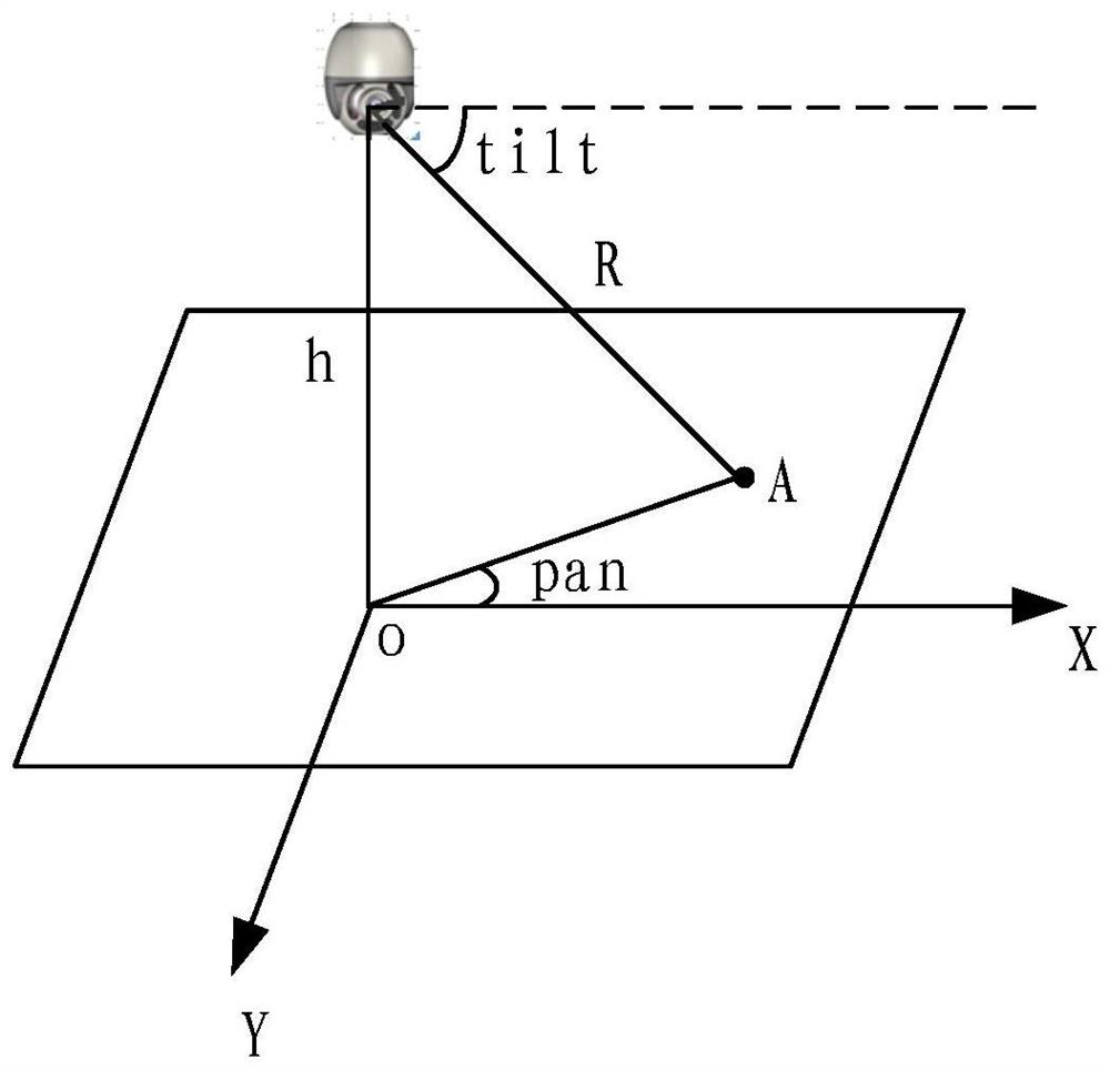
[0167] See Figure 8 , is a flow chart of another embodiment of a method for linkage between a radar and a ball camera shown in an exemplary embodiment of the present application, which is used to pre-calibrate and solve the best observation magnification of the ball camera, that is, the second setting of the Z coordinate value Determine the algorithm, the method in the above figure 2 and Figure 5 Based on the method shown, the following steps may be included:
[0168] Step 801: Obtain at least two sets of calculation parameters, each set of calculation parameters includes the distance between the dome camera and the target object, and the best observation magnification of the dome camera.
[0169] Step 802: Solve a second setting algorithm for calculating the optimal observation magnification of the dome camera according to the distance between the dome camera and the target object based on at least two sets of calculation parameters.
[0170] The above steps 801 to 802 ...
PUM
 Abstract
Description
Claims
Application Information
 - R&D Engineer
- R&D Manager
- IP Professional
- Industry Leading Data Capabilities
- Powerful AI technology
- Patent DNA Extraction
Browse by: Latest US Patents, China's latest patents, Technical Efficacy Thesaurus, Application Domain, Technology Topic, Popular Technical Reports.
© 2024 PatSnap. All rights reserved.Legal|Privacy policy|Modern Slavery Act Transparency Statement|Sitemap|About US| Contact US: help@patsnap.com