


Quick Research
Generate reliable direction feasibility study reports for your R&D in just a few steps.

Technical Q&A
Discover and master advanced knowledge NOW. Basics, ideas, possibilities, all at once.

Find Solutions
As an expert in R&D theories, this can generate solutions to your technical problems instantly.

Evaluate Feasibility
Analyze your overall solution with one click, know your potential R&D risks in advance.

Monitor Landscape
Get weekly tech updates, stay abreast of the latest tech innovations and key insights.
A method of partitioning
A defense area and camera technology, which is applied in anti-theft alarms, anti-theft alarm mechanical start-ups, instruments, etc., can solve the problems of light length error, insufficient precision, and incomplete coverage of the camera field of view, so as to reduce monitoring blind spots and improve linkage accuracy.
- Summary
- Abstract
- Description
- Claims
- Application Information
AI Technical Summary
Problems solved by technology
Method used
Image

Examples
Embodiment 1
[0027] Defense zone is an important concept in the security system. It associates basic sensor alarms with alarm handling devices, helping users to monitor and control the on-site situation conveniently and quickly. The division of defense zones directly affects the accuracy of alarm reporting and linkage control, so how to divide defense zones is very critical.
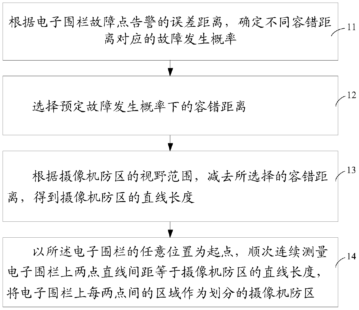
[0028] Therefore, the present invention provides a method for zone division, the flow diagram of which is as follows figure 1 shown, including:
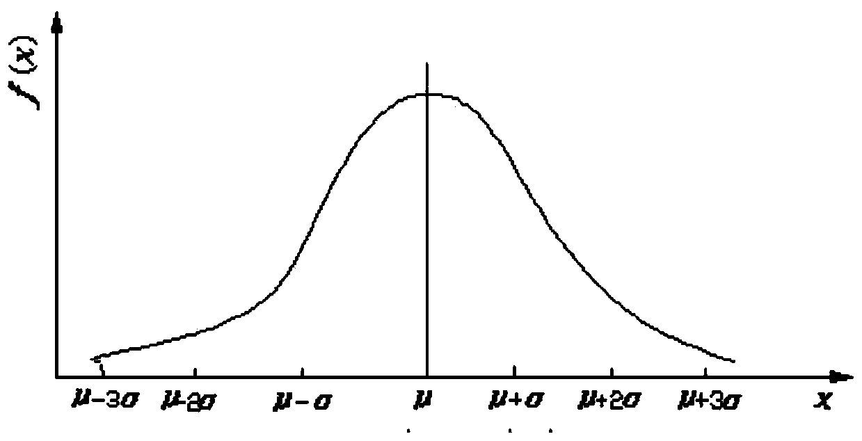
[0029] Step 11, according to the error distance of the electronic fence fault point alarm, determine the fault occurrence probability corresponding to different fault tolerance distances;
[0030] Step 12, selecting the fault-tolerant distance under the predetermined probability of fault occurrence;
[0031] Step 13, according to the field of view of the camera defense zone, subtract the selected fault tolerance distance to obtain the straight line length of the camera de...
Embodiment 2
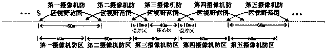
[0086] In order to see the accident point clearly, the present invention designs multi-channel video to capture scene images at the same time. A geo-fence fault point is covered by the prefab field of view of the main camera and the prefab field of view of two auxiliary cameras. The division of the camera defense zone and the way of rolling and crossing the view range of the camera defense zone are the same as those in the first embodiment. The difference is that three cameras can be linked for all-round surveillance. The specific method is as follows:
[0087] Step 51, establishing a mapping relationship between each camera defense zone and the prefabricated positions of the three cameras on the monitoring platform;
[0088] Among them, establishing the mapping relationship between each camera defense area and the prefabricated positions of the three cameras on the monitoring platform includes:
[0089] Starting from the starting point, measure the linear length of the ove...
PUM
 Abstract
Description
Claims
Application Information
 - R&D Engineer
- R&D Manager
- IP Professional
- Industry Leading Data Capabilities
- Powerful AI technology
- Patent DNA Extraction
Browse by: Latest US Patents, China's latest patents, Technical Efficacy Thesaurus, Application Domain, Technology Topic, Popular Technical Reports.
© 2024 PatSnap. All rights reserved.Legal|Privacy policy|Modern Slavery Act Transparency Statement|Sitemap|About US| Contact US: help@patsnap.com