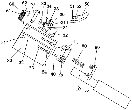
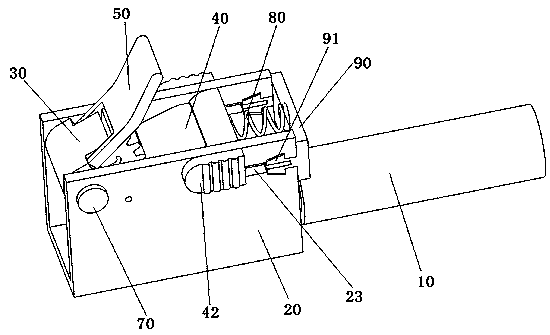
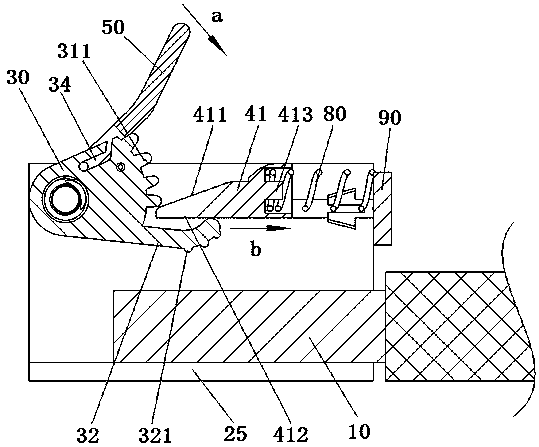
Electrical wiring terminal
A technology of electrical wiring and terminals, applied in the direction of multi-core cable end parts, clamping/spring connection, etc., can solve the problems of poor stability, easy failure of crimping, etc., to achieve flexible form, optimized force structure, and simple overall layout Effect
- Summary
- Abstract
- Description
- Claims
- Application Information
AI Technical Summary
Problems solved by technology
Method used
Image
Examples
Embodiment 2
[0070]Embodiment 2 of the electrical connection terminal in the present invention: the difference from the above embodiment is that in this embodiment, the wire enters and exits the housing along the left and right directions, and the crimping body is guided and assembled on the housing along the up and down direction, and the crimping body When going down, the wire can be pressed to the connecting conductor, and when the wire pressing body is going up, the wire can be released to make the wire withdraw from the housing. One of the casing and the crimping body is provided with a sliding groove, and the other is provided with a slider, and the sliding groove cooperates with the guide of the sliding block so that the crimping body can move and be assembled on the housing. The lock tongue is arranged in the housing along the left and right directions, and a lock tongue elastic member is still arranged in the housing to provide an active force. The side of the crimping body facing...
Embodiment 3
[0071] Embodiment 3 of the electrical connection terminal in the present invention: the difference from the above embodiments is that in this embodiment, the conductive part used to electrically connect with the wire entering the housing is arranged on the crimping body, when the crimping body itself faces When the wire moves to compress the wire, the electrical connection between the conductive part on the wire pressing body and the wire is also realized, and the conductive part on the wire pressing body can be electrically connected with other conductors.
[0072] Embodiment 4 of the electrical connection terminal in the present invention: the difference from the above-mentioned embodiments is that in this embodiment, the locking part that locks and cooperates with the crimping body is fixedly arranged on the housing, and the crimping body can be rotated and set It can be moved in a straight line and set in the housing. The locking part is a locking tooth arranged along the ...
Embodiment 5
[0073] Embodiment 5 of the electrical connection terminal in the present invention: the difference from the above embodiments is that the crimping body in this embodiment includes a cylinder, and the cylinder is rotatably assembled on the housing. On the surface, a lock hole or a lock groove adapted to the lock tongue is provided. The hole edge of the lock hole can stop and cooperate with the lock tongue to limit the position of the crimping body. The lock hole can be a square hole, and the hole edge of the square hole can stop and cooperate with the dead bolt during the rotation stroke of the cylinder, and is not limited to the scheme of setting a plurality of ribs and using the ribs to form the lock groove.
[0074] Embodiment 6 of the electrical connection terminal in the present invention: the difference from the above embodiments is that in this embodiment, the operating arm is fixedly arranged on the crimping body, and the position of the operating arm relative to the cr...
PUM
 Abstract
Description
Claims
Application Information
 - R&D
- Intellectual Property
- Life Sciences
- Materials
- Tech Scout
- Unparalleled Data Quality
- Higher Quality Content
- 60% Fewer Hallucinations
Browse by: Latest US Patents, China's latest patents, Technical Efficacy Thesaurus, Application Domain, Technology Topic, Popular Technical Reports.
© 2025 PatSnap. All rights reserved.Legal|Privacy policy|Modern Slavery Act Transparency Statement|Sitemap|About US| Contact US: help@patsnap.com


